
Disk drive

a technology of disk drive and drive plate, which is applied in the direction of maintaining head carrier alignment, recording information storage, instruments, etc., can solve the problems of data loss, height fluctuation, data loss,

Inactive Publication Date: 2003-10-30
HITACHI GLOBAL STORAGE TECH JAPAN LTD +1
View PDF2 Cites 47 Cited by
  • Summary
  • Abstract
  • Description
  • Claims
  • Application Information

AI Technical Summary

Problems solved by technology

The vibrations produce a flying-height fluctuation, which poses a problem of impairing the reliability of magnetic disk drive.
In the worst case, a head collides with a disk, so that there arises a problem in that the data stored on the disk is destroyed, or a head element of transducer for recording / reproducing data is destroyed.

Method used


Image

  • Disk drive
  • Disk drive
  • Disk drive

Examples


Embodiment Construction

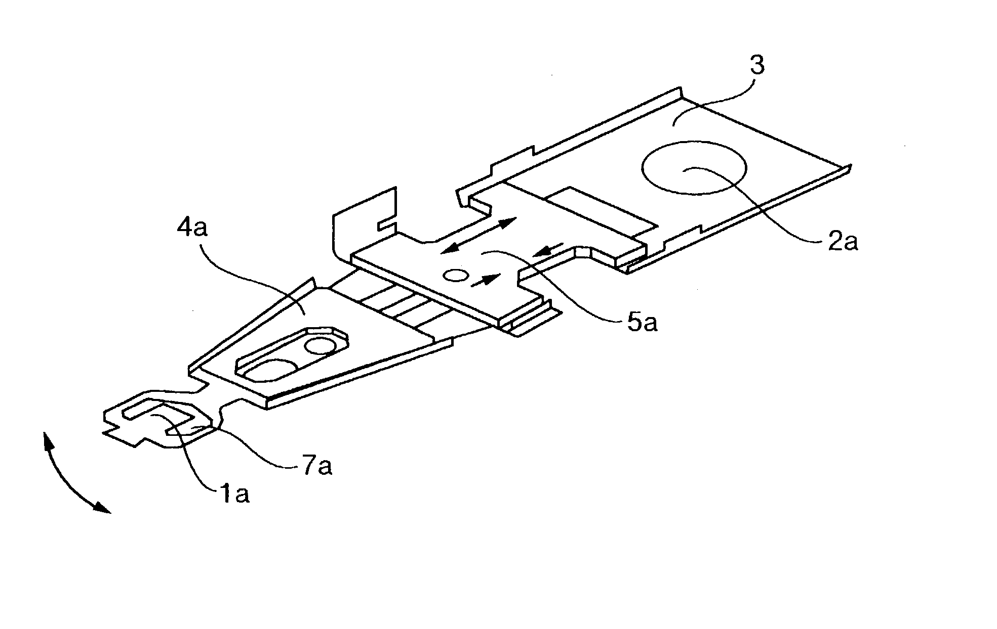
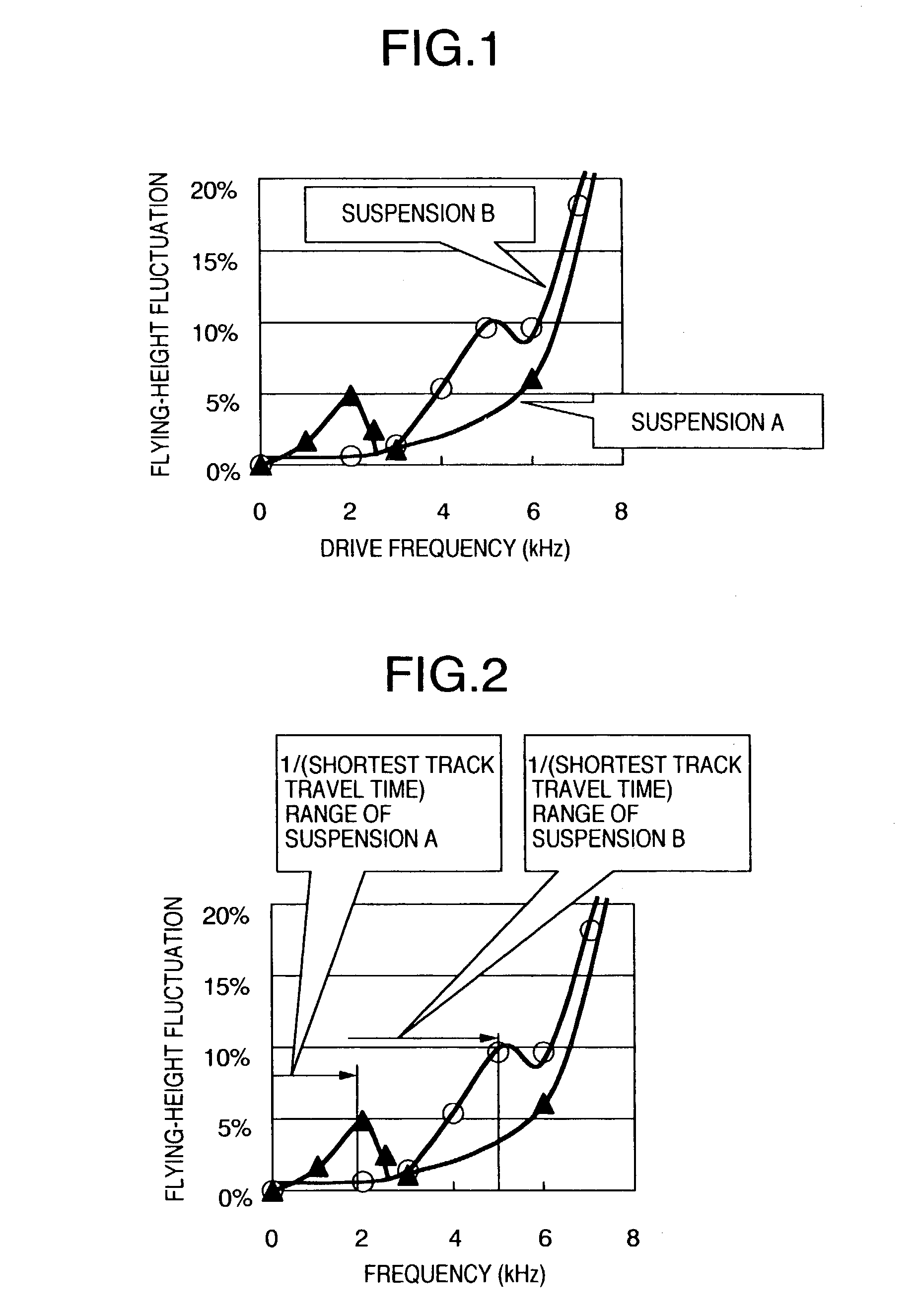
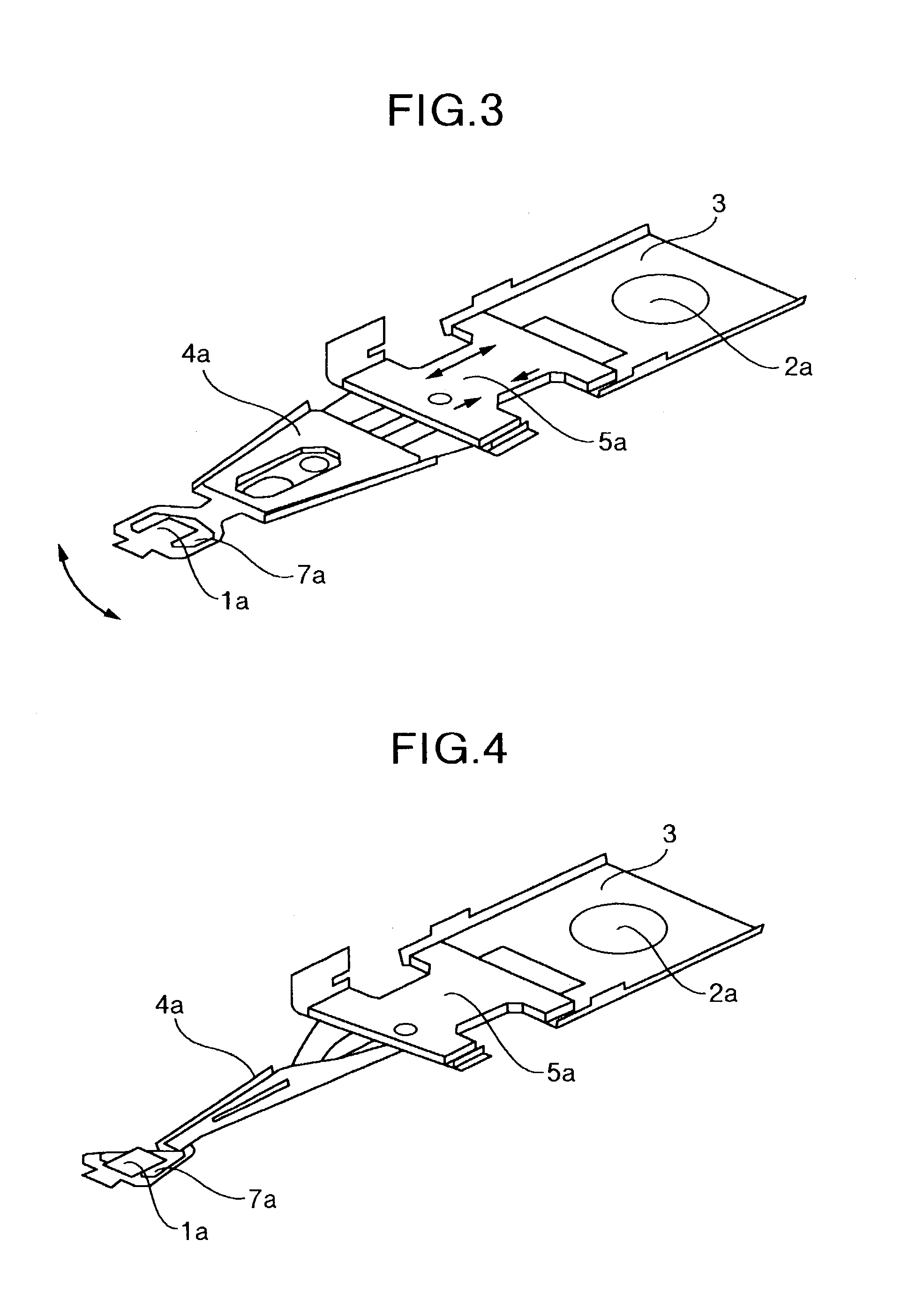
[0021] A magnetic disk drive using a suspension type fine actuator in accordance with an embodiment of the present invention will now be described in detail with reference to FIGS. 1 to 8. FIG. 1 is a characteristic diagram showing the relationship between flying-height fluctuation and piezo drive frequency in the suspension type fine actuator in accordance with this embodiment. FIG. 2 is a graph showing the relationship between flying-height fluctuation and head travel vibration of the shortest track at the drive frequency shown in FIG. 1. FIG. 3 is a perspective view showing a construction of a suspension A in accordance with this embodiment. FIG. 4 is a perspective view showing a vibration mode of first torsion mode of the suspension A.

[0022] FIG. 5 is a perspective view showing a construction of a suspension B in accordance with this embodiment. FIG. 6 is a perspective view showing a vibration mode of first torsion mode of the suspension B in accordance with this embodiment. FIG...


PUM

PropertyMeasurementUnit
distanceaaaaaaaaaa
thicknessaaaaaaaaaa
thicknessaaaaaaaaaa

Abstract

There is provided a magnetic disk drive in which a flying-height fluctuation produced by the operation of a fine actuator is decreased, the reliability is high, and recording density is high. For this purpose, the magnetic disk drive is configured as described below. The magnetic disk drive has a suspension including a base plate connected to a carriage, a load beam fitted with a slider, and a fine actuator which is provided on the base plate and finely moves the load beam. The configuration is such that the shortest track travel time using the fine actuator is larger than the inverse number of the local maximum of a flying-height fluctuation frequency of the suspension by the fine actuator. Also, the configuration is such that the shortest track travel time using the fine actuator is larger than the inverse number of the natural frequency of first torsion mode of the suspension by the fine actuator.

Description

[0001] The present invention relates to a disk drive used for an external storage device of a computer and, more particularly, to a magnetic disk drive using a suspension type fine actuator.PRIOR ART[0002] A head positioning actuator aiming at high recording density of a magnetic disk constitutes a two-stage actuator by means of gang control with a VCM (voice coil motor). It achieves highly accurate head positioning and also improves track density. A specific configuration of two-stage actuator is described in "Microactuator for Magnetic Disk Drive" in Journal of the Institute of Electrical Engineers of Japan, Vol. 120, No. 11, pp. 690-692 (November, 2000). According to this paper, the first-stage actuator is an ordinary VCM, and the second-stage actuator, that is, a fine actuator uses a piezoelectric element.[0003] The fine actuators are classified into suspension actuators, slider actuators, and head actuators according to a difference in drive position thereof.[0004] One example ...

Claims


Application Information

Patent Timeline
Patent Type & Authority Applications(United States)
IPC IPC(8): G11B5/55G11B21/10G11B5/596G11B21/21
CPCG11B5/5552G11B5/4873
Inventor NAKAMURA, SHIGEOTAKAHASHI, HARUHIDEWAKATSUKI, KOUSAKU
Owner HITACHI GLOBAL STORAGE TECH JAPAN LTD
Learn More