
Timeout determination method and apparatus

a timeout determination and timeout technology, applied in the field of timeout determination methods and apparatuses, can solve the problems of requiring considerable memory, critical memory size, and needing to update the entire state table in regular intervals

Inactive Publication Date: 2003-10-30
GOOGLE LLC
View PDF7 Cites 22 Cited by
  • Summary
  • Abstract
  • Description
  • Claims
  • Application Information

AI Technical Summary

Benefits of technology

[0014] With the unique and unobvious combination of features of the present invention, the invention has the advantage that the subset of bits of the counter, that subset also being referred to as a "window", does not have a fixed position but is variable in that position. This variability can be exploited in a way that trades resolution of the window against wrap around time of that window. This is particularly useful when the method is used in a system that is designed to cope with different time-out values, since the window position can be adapted to the different time-out values by shifting the window.
[0028] The apparatus in an exemplary embodiment of the present invention, also can include an input for the inaccuracy-value, thereby allowing a user or administrator to communicate to the apparatus the desired inaccuracy-value. An apparatus with this feature would provide even more freedom in system design.

Problems solved by technology

With several thousand flows on a high-speed network link, the maintenance and handling of a per-flow state require considerably large memories.
High-speed systems require on-chip implementation of this memory, and here memory size is critical.
However, a major drawback of this solution, apart from relying on randomness, is the need to update the entire state table in regular intervals.
However, the window is non-adjustable in its size or position within the larger-format time-stamp.

Method used


Image

  • Timeout determination method and apparatus
  • Timeout determination method and apparatus
  • Timeout determination method and apparatus

Examples


Embodiment Construction

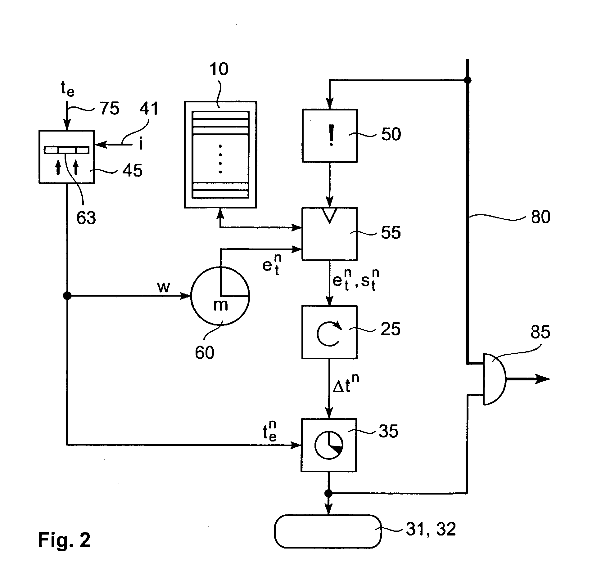
[0033] Referring now to the drawings, and more particularly to FIGS. 1-2, there are shown exemplary embodiments of the method and structures according to the present invention.

[0034] Exemplary Embodiments

[0035] In the following, the various exemplary embodiments of the invention are described. The superscribed index n is used to make clear that the indexed variable has a width of n bits.

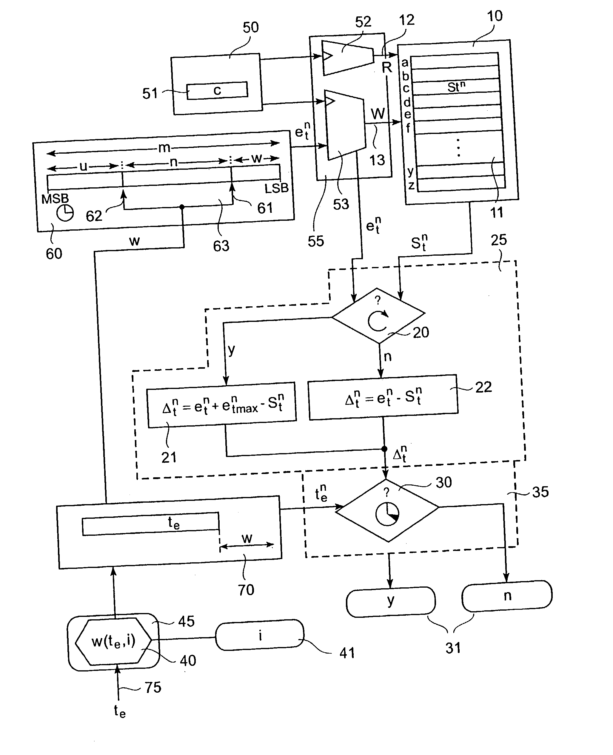
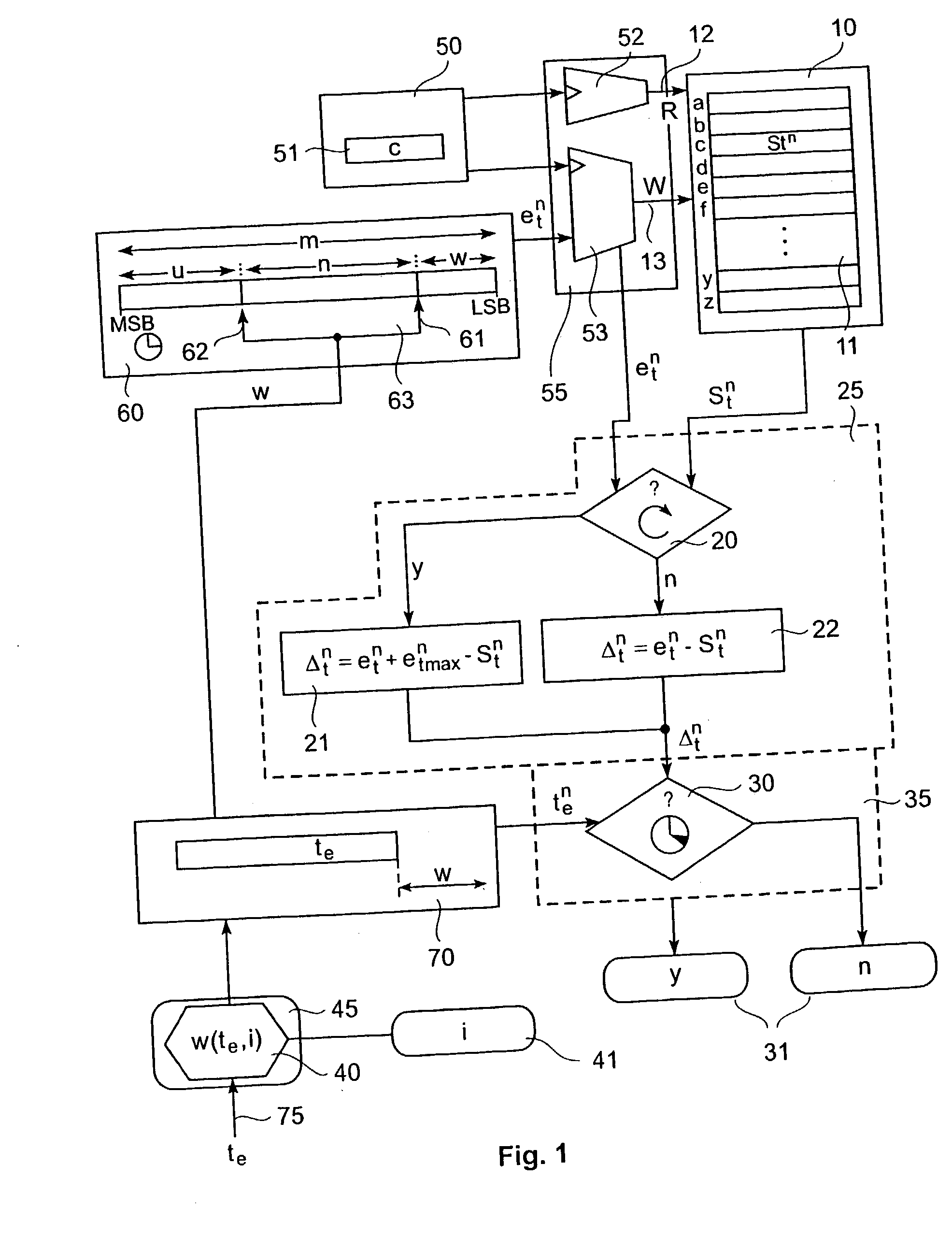
[0036] FIG. 1 is a schematic diagram showing a mechanism for determining whether an event-occurrence lies after a predetermined timeout-value.

[0037] Specifically, an event-trigger input 50 is arranged at an input side of a memory read / write controller 55 for a time-stamp memory 10. Memory 10 is connected to a time-out determinator 35 via a time-difference determinator 25. A bit-position determinator 45 with a timeout-value input 75 and an inaccuracy-value input 41 is arranged at an input of a timeout-value memory 70. Memory 70 is connected to the time-out determinator 35 and to an m-bit time counter ...


PUM


Abstract

A method (and apparatus) for determining, in a system including an m-bit time counter, whether an event-occurrence time lies after a predetermined timeout-value, includes reading out of a time-stamp memory a stored time-stamp value, determining the time-difference between the time-stamp value and the event-occurrence time, and determining whether the time-difference is larger than the predetermined timeout-value. The event-occurrence time is represented by a subset of the bits of the m-bit time counter, the subset being determined by a plurality of parameters including any two of a lower bit-position, an upper bit-position, and a subset width. The lower bit-position is dependent on the predetermined timeout-value.

Description

[0001] 1. Field of the Invention[0002] The present invention generally relates to a method and apparatus for determining whether an event-occurrence time lies after a predetermined timeout-value.[0003] 2. Description of the Related Art[0004] Communication systems move more and more towards keeping a state for individual data flows (e.g., for quality-of-service (QOS) features). With several thousand flows on a high-speed network link, the maintenance and handling of a per-flow state require considerably large memories. High-speed systems require on-chip implementation of this memory, and here memory size is critical. Even single bits that are saved on a per-flow state can help reduce the memory size, and hence the chip size, and thus make it cheaper.[0005] A common piece of information that is kept as a part of a flow state is a time-stamp (e.g., the point in time) when the last packet of a flow arrived. These time stamps are mostly used to compare the idle-time of a flow (i.e., the ...

Claims


Application Information

Patent Timeline
Patent Type & Authority Applications(United States)
IPC IPC(8): H04L12/24
CPCH04L69/28H04L43/026
Inventor DITTMANN, GEROHERKERSDORF, ANDREAS
Owner GOOGLE LLC
Learn More