Tranducerized torque wrench

a torque wrench and transducer technology, applied in the direction of manufacturing tools, portable power-driven tools, drilling pipes, etc., can solve the problems of limiting the applicability of devices and the variability of output speed and torqu

Active Publication Date: 2004-03-04
JERGENS
View PDF13 Cites 54 Cited by
  • Summary
  • Abstract
  • Description
  • Claims
  • Application Information

AI Technical Summary

Problems solved by technology

Further, some prior art devices rely on power sources such as compressed air to drive the associated motor, which can limit the applicability of a device since producing compressed air requires space

Method used


Image

  • Tranducerized torque wrench
  • Tranducerized torque wrench
  • Tranducerized torque wrench

Examples


Embodiment Construction

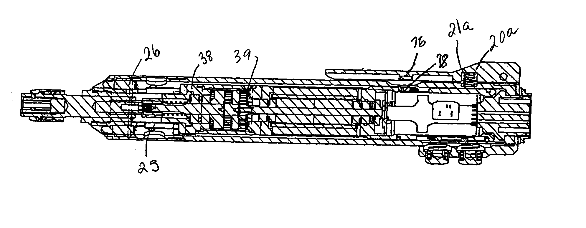
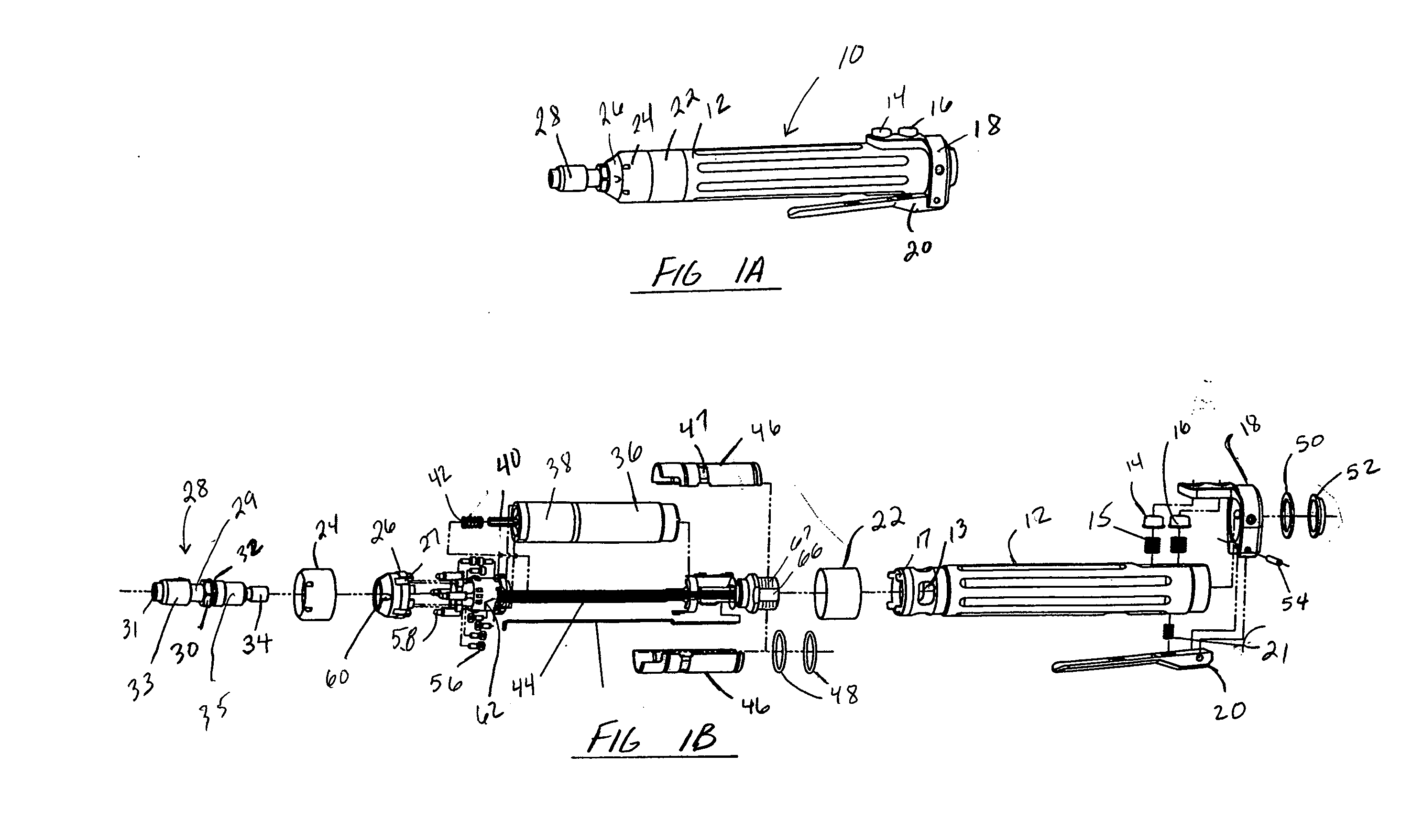
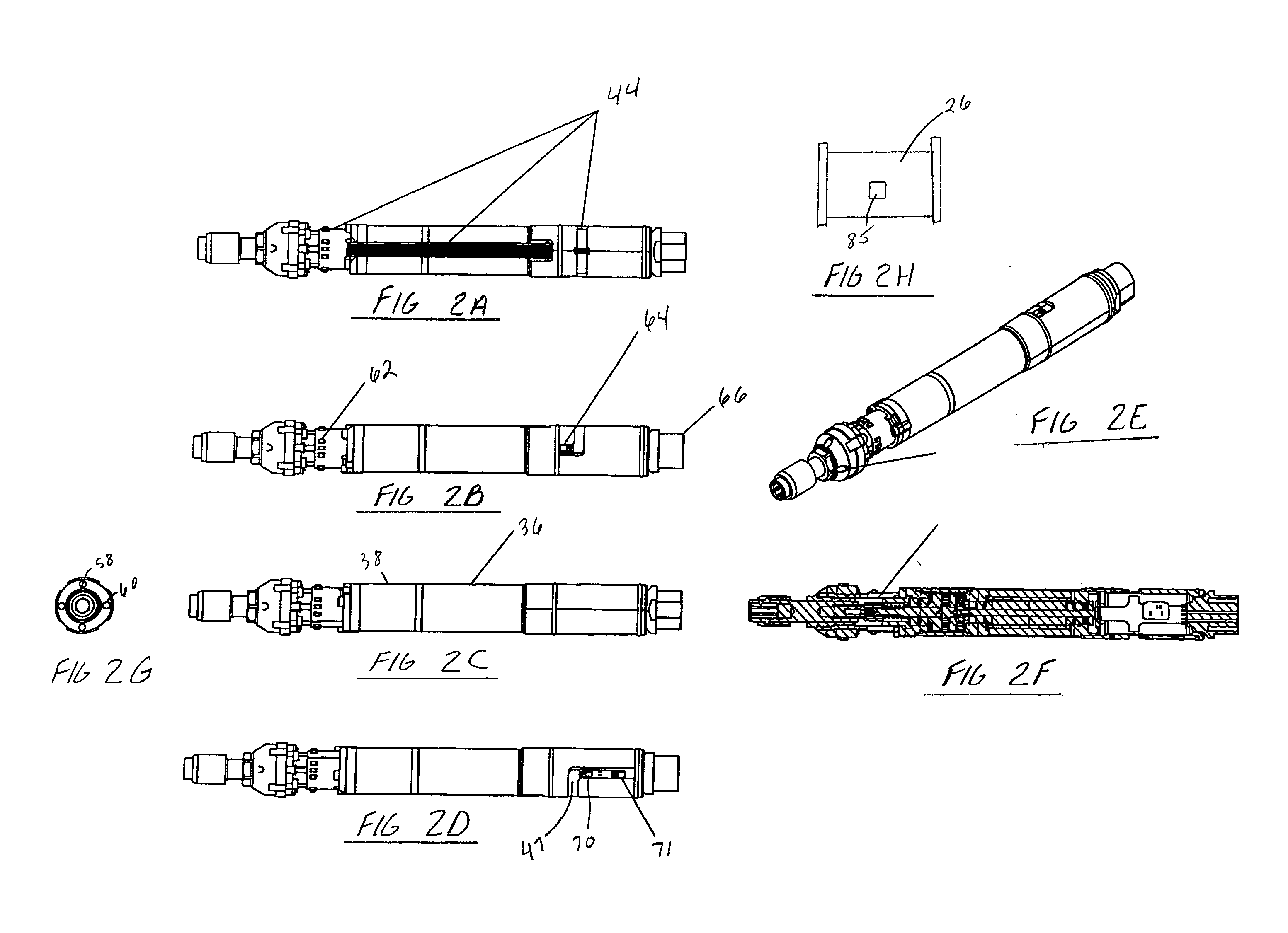
[0050] In an exemplary embodiment of the present invention the motor 36 is a Maxon EC motor, model EC 22, 22 mm, brushless, and 50 Watt that can be purchased from Maxon Precision Motors, inc., 838 Mitten Road, Burlingame, Calif. 94010. The gear box 38 comprises two gear stages, where the two stages provide a conversion of speed to torque of 6.75:1 and 4.285:1 respectively. Thus the overall torque conversion is an increase of 28.92:1 (6.75.times.4.285) with a corresponding reduction in velocity. The preferred torque capacity is 20 in-lbs with a rotational velocity of 1,100 rpm. To maximize torque / velocity conversion while minimizing space, the preferred gear system is a planetary gear system. In this system the first stage sun gear is attached to the motor output shaft and engages a series of three planetary gears. The planetary gears are all attached to a planet carrier, from which extends a second sun gear into the next planetary gear stage. The output shaft of the second gear stag...


PUM


Abstract

Disclosed herein is a variable speed tool useful for use with securing or removing industrial fasteners. The tool also includes a means to torque the fastener to a certain precise torque. The tool can be used with an associated controller that provides control commands to the tool.

Description

[0001] This application claims priority from co-pending U.S. Provisional Application No. 60 / 407,786, filed Sep. 3, 2002, the full disclosure of which is hereby incorporated by reference herein.[0002] 1. Field of the Invention[0003] The invention relates generally to the field of automatic drivers for fasteners. More specifically, the present invention relates to an apparatus for driving fasteners that is automatic and controllable. Yet more specifically, the present invention relates to a device for driving fasteners, where the apparatus delivers a specified torque. Yet even more specifically, the present invention relates to an automatic apparatus where the torque delivered is controllable from about 1 in-lb up to about 50 in-lb.[0004] 2. Description of Related Art[0005] Many prior art devices exist that are capable of driving fasteners apertures, such as threaded bolt holes and the like. These tools typically require the user to activate a switch or a trigger to activate the devic...

Claims


Application Information

Patent Timeline
IPC IPC(8): B25B21/00B25B23/14B25B23/147B25F5/02
CPCB25B21/00B25F5/026B25B23/147B25B23/14
Inventor MILLER, JERRY EDWARD
Owner JERGENS
Why Eureka
Try Eureka