Disk drive

a technology for disk drives and drives, applied in the direction of casings/cabinets/drawers, instruments, casings/cabinets/drawers, etc., can solve the problem of increasing the manufacturing cost of disk drives 101

Inactive Publication Date: 2004-03-25
PIONEER CORP
View PDF5 Cites 1 Cited by
  • Summary
  • Abstract
  • Description
  • Claims
  • Application Information

AI Technical Summary

Problems solved by technology

Inevitably, the metal plate for the top wall 106a becomes large, thereby increasing the manufacturing cost of the disk drive 101.

Method used


Image

  • Disk drive
  • Disk drive
  • Disk drive

Examples


Embodiment Construction

)

[0025] An embodiment of the present invention will be described, with reference to the accompanying drawings.

[0026] [Arrangement of Disk Drive]

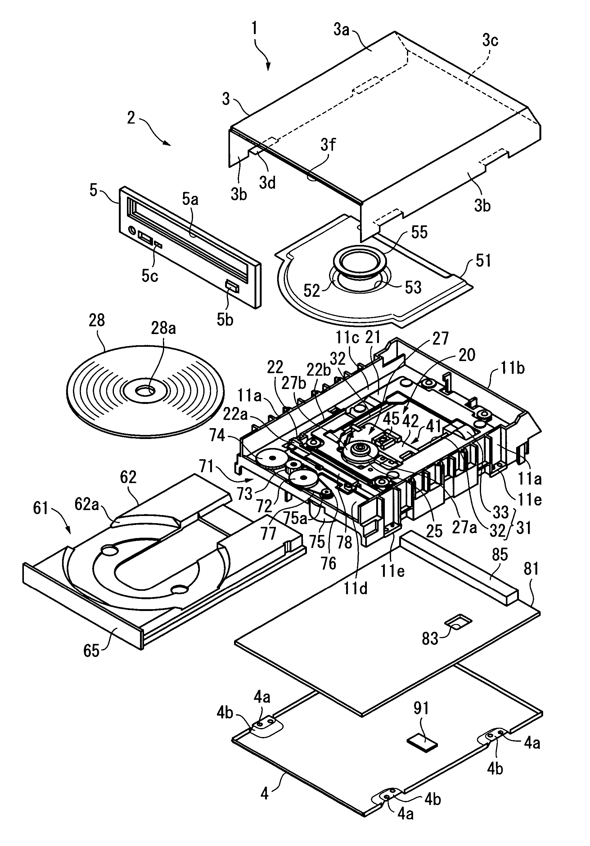
[0027] FIG. 3 is an exploded perspective view of a disk drive according to an embodiment of the present invention.

[0028] As FIG. 3 shows, a disk drive 1 has a main unit 20 and an outer case 2. The outer case 2 covers the main unit 20.

[0029] The outer case 2 includes an upper case 3, a lower case 4, and a decorative panel 5. The upper case 3 is made of metal and opens at the bottom and the front. The lower case 4 is made of metal and closes the bottom of the upper case 3. The decorative panel 5 is made of synthetic resin and closes the front of the upper case 3.

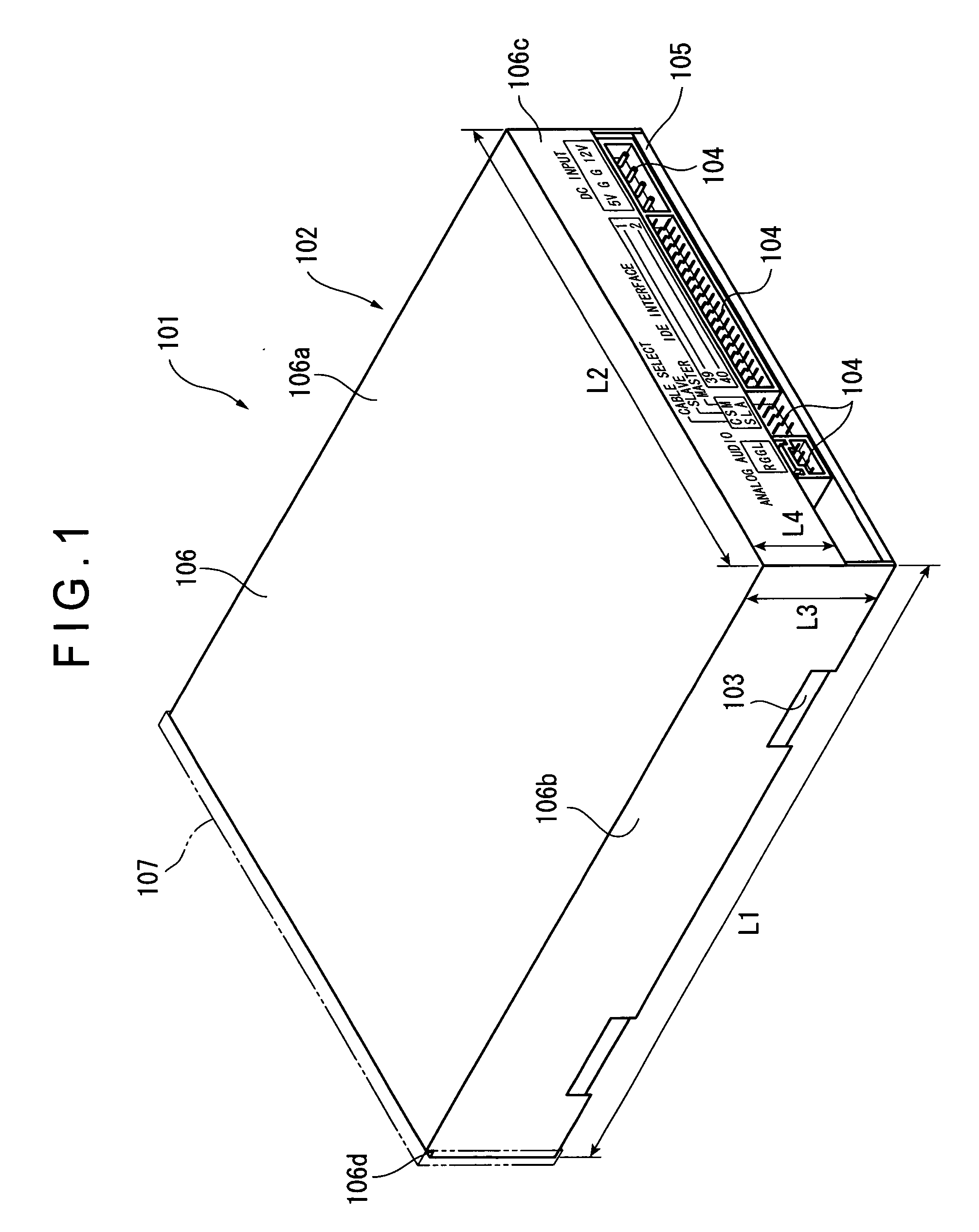
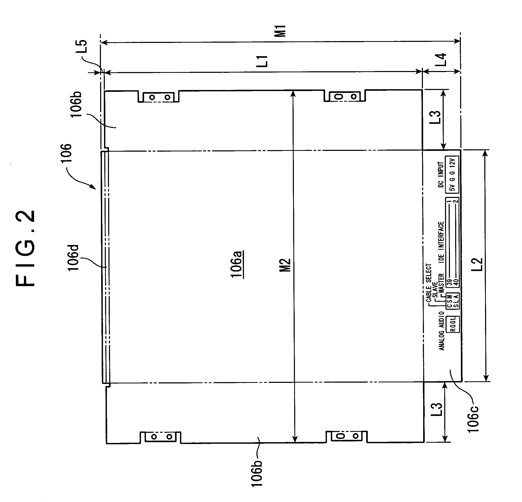
[0030] FIG. 4 is a perspective view of the disk drive 1, and FIG. 5 is a development view of the upper case 3.

[0031] As seen from FIGS. 4 and 5, the upper case 3 is composed of a top wall 3a (horizontal plate), two side walls 3b, a rear wall 3c (inclined plate), and a panel-holding str...


PUM

PropertyMeasurementUnit
obtuse angleaaaaaaaaaa
poweraaaaaaaaaa
length L1aaaaaaaaaa

Abstract

A disk drive includes a main unit and an outer case (2). The main unit includes a disk-driving unit for rotating a disk, a data-reproducing unit for reproducing data from the disk, and a drive unit for moving the data-reproducing unit relative to the disk. The outer case (2) has a top wall (3a) and a rear wall (3c). The top wall (3a) opposes the main unit. The rear wall (3c) extends from the rear edge of the top wall (3a), is gently inclined and covers the rear part of the main unit. The rear wall (3c) serves as a guide when the disk drive is inserted into a slot of an apparatus. In addition, the metal plate used to form the outer case (2) can be smaller than otherwise.

Description

[0001] 1. Field of the Invention[0002] The present invention relates to a disk drive that includes a main unit and an outer case covering the main unit.[0003] 2. Description of Related Art[0004] Disk drives for reproducing or reproducing / recording data from and on optical disks such as DVDs (Digital Versatile Disks) and CDs (Compact Disks) have been widely used. A disk drive having such a structure as shown in FIG. 1 is known.[0005] The disk drive 101 illustrated in FIG. 1 has an outer case 102 that is made of metal, shaped like a box and open at one side. The outer case 102 contains a frame 103 that is made of synthetic resin.[0006] The frame 103 holds a disk-driving unit, a data-reproducing unit and a main unit. The disk-driving unit (not shown) is designed to rotate an optical disk. The data-reproducing unit (not shown) has a photosensor for recording or reproducing data on or from the optical disk. The main unit has a drive unit for moving the data-reproducing unit relative to t...

Claims


Application Information

Patent Timeline
Patent Type & Authority Applications(United States)
IPC IPC(8): H05K5/02G11B17/04G11B25/04G11B33/02G11B33/12
CPCG11B17/056G11B33/02G11B25/043
Inventor KONNO, YOUICHI
Owner PIONEER CORP
Why Eureka
Try Eureka