
Eureka
For R&D, Eureka makes reading and utilizing patents & technical documents easy.
Eureka AIR
Designed for self-driven R&D workflows. Generate viable solutions, solve complex R&D challenges, empower your innovation with AI.

Eureka Materials
Designed for material experts only. Revolutionize your material R&D, from search, analyze, to developing new materials.

TechResearch
Generate reliable direction feasibility study reports for your R&D in just a few steps.

TechSeek
Discover and master advanced knowledge NOW. Basics, ideas, possibilities, all at once.

TechMind
As an expert in R&D Theories, TechMind can generates customized viable solutions instantly.

TechRisk
Analyze your overall solution with one click, know your potential R&D risks in advance.

TechMonitor
Get weekly tech updates, stay abreast of the latest tech innovations and key insights.
Combination push button and bottle lever for activating a water valve in a product dispenser
- Summary
- Abstract
- Description
- Claims
- Application Information
AI Technical Summary
Problems solved by technology
Method used
Image

Examples
Embodiment Construction
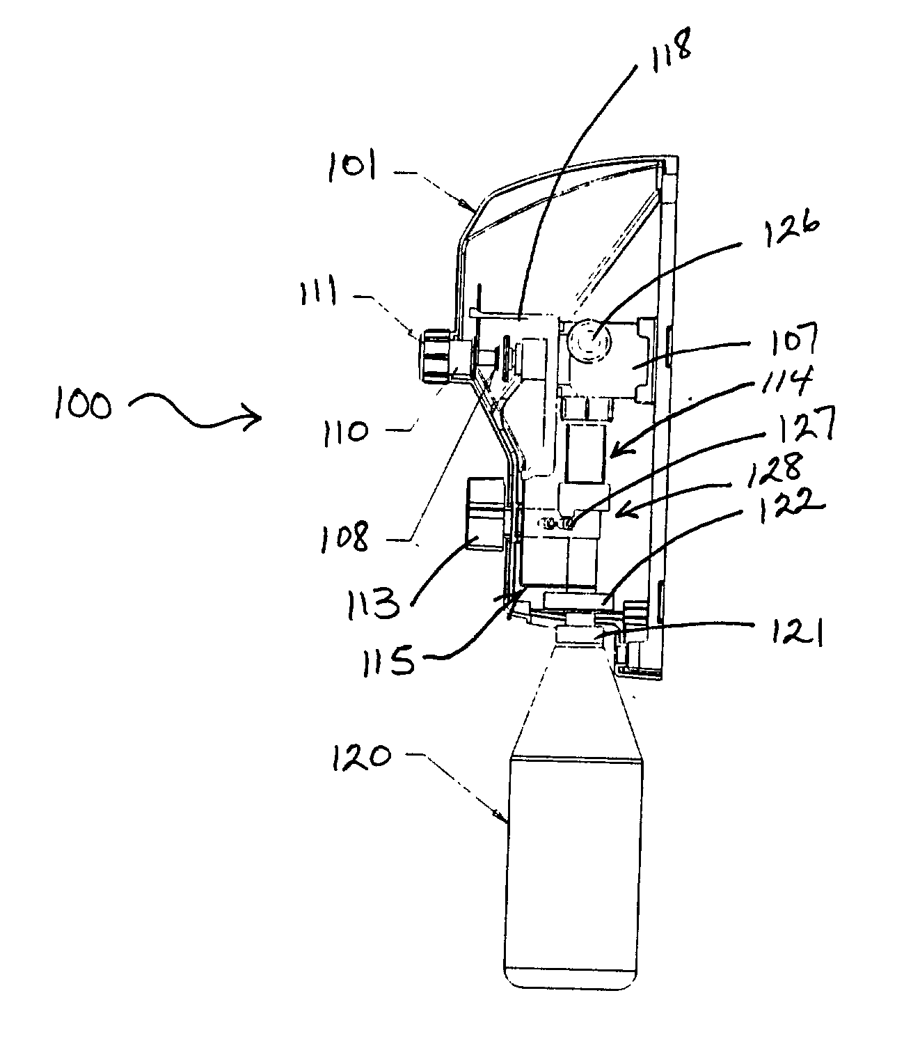
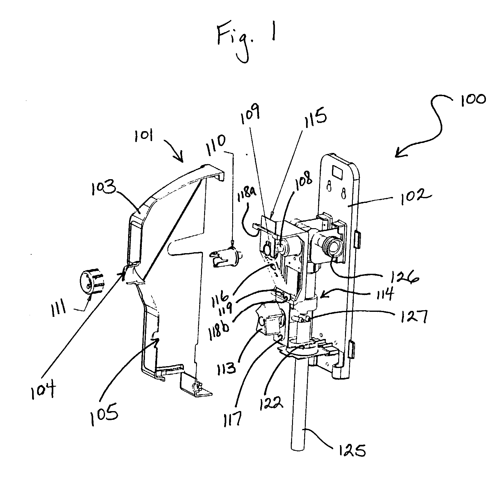
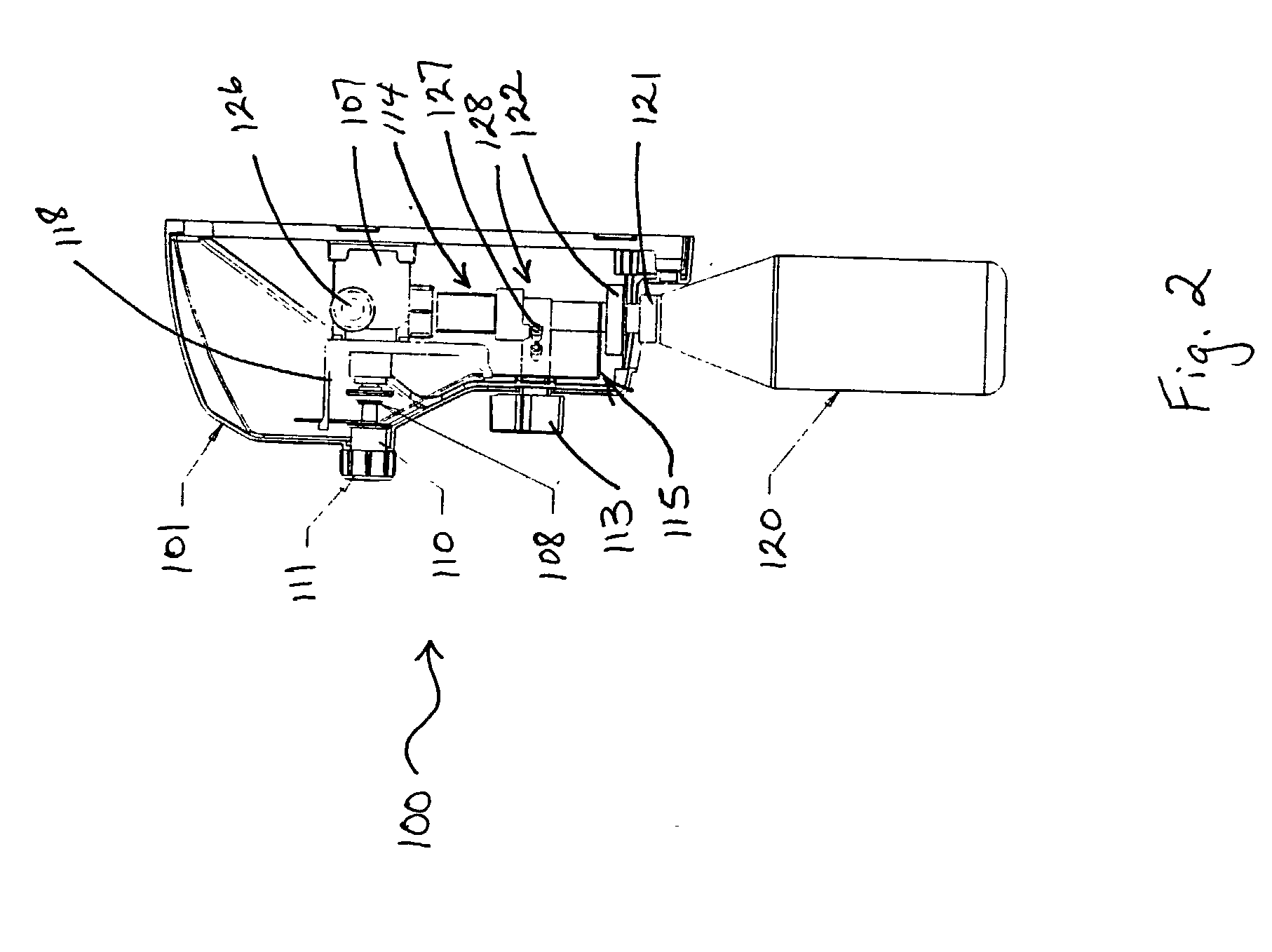
[0020] A dispenser constructed according to the principles of the present invention is designated by the numeral 100 in the drawings.
[0021] The dispenser 100 is a dispenser for filling both spray bottles and mop buckets or other suitable containers well known in the art with a diluted product. The present invention is a modification of the dispenser disclosed in U.S. Pat. No. 5,832,972 by Thomas et al., which is incorporated by reference herein. The present invention modifies the slide actuator by adding a slot through which the activation switch extends. Therefore, the activation switch may be activated in two different ways. One way is to simply manually press the push button operatively connected to the activation switch. The second way is to use a spray bottle to press the member or bottle lever in an upward direction thereby sliding the actuator upward to press the activation switch. The activation switch activates the water valve of the dispenser to fill the container. Althoug...
PUM
 Abstract
Description
Claims
Application Information
 - R&D Engineer
- R&D Manager
- IP Professional
- Industry Leading Data Capabilities
- Powerful AI technology
- Patent DNA Extraction
Browse by: Latest US Patents, China's latest patents, Technical Efficacy Thesaurus, Application Domain, Technology Topic, Popular Technical Reports.
© 2024 PatSnap. All rights reserved.Legal|Privacy policy|Modern Slavery Act Transparency Statement|Sitemap|About US| Contact US: help@patsnap.com