Energized restraining gasket for mechanical joints of pipes

a technology of mechanical joints and gaskets, applied in the direction of hose connections, cable terminations, other domestic objects, etc., can solve the problems of increasing the cost and time of installation, meaningless difficulty, and inconvenient to have multiple additional bolting requirements on the underside of the pip

Inactive Publication Date: 2004-04-22
US PIPE & FOUNDRY
View PDF86 Cites 30 Cited by
  • Summary
  • Abstract
  • Description
  • Claims
  • Application Information

AI Technical Summary

Benefits of technology

[0015] As suggested by the foregoing discussion, an an exemplary and non-exclusive alternative object of this invention is to provide a gasket interchangeable with gaskets of standard mechanical joints which allows for the transformation of the joint into a restrained joint without the need for any reconfiguration or adaptation of the bell, spigot, or gland of the mechanical joint involved.
[0016] A further exemplary and non-exclusive alternative object is to provide a dynamic connection for pipes that does not require high insertion pressures.

Problems solved by technology

Due to thrust forces, earth movement, and external mechanical forces exerted on pipes, the industry has focused substantial attention on the problem of maintaining connections between adjacent lengths of pipe after installation.
Meaningful difficulty has been experienced in the industry, however, in applying these connections to fittings, where it may be impracticable to secure the fitting sufficiently to exert the high installation pressures necessary initially to push the spigot into the bell in such configurations.
When a pipe is installed in a ground-bedded environment, it is typically inconvenient to have multiple additional bolting requirements on the underside of the pipe as laid.
Such underside boltings increase the cost and time of installation.
If, however, the bolt-in locking scheme employs only a few bolt locations, the inward pressure of the bolts may in some conditions tend to deform the cross-sectional profile of the spigot.
For example, employment of only three bolt locations in some circumstances may exhibit an undesirable possibility of deforming the spigot into a slightly triangular shape.
It will be noted by those reasonably skilled in the art that each of these configurations also suffers from practical issues, such as the expense of manufacture of additional components and the fact that additional components increase the potential for unacceptable failure.
Additionally, locations in which pipes are run rarely are as stable as commonly believed.
In fact, pipes may be run above ground, in which cases such pipes do not enjoy the benefit of any stability enhancing factors of bedding or trenched installation.

Method used


Image

  • Energized restraining gasket for mechanical joints of pipes
  • Energized restraining gasket for mechanical joints of pipes
  • Energized restraining gasket for mechanical joints of pipes

Examples


Embodiment Construction

. Those skilled in the art will understand that the specificity provided herein is intended for illustrative purposes with respect to the inventor's most preferred embodiment, and is not to be interpreted as limiting the scope of the invention. References to "pipe" herein shall be understood equally to refer to any pipe length, appurtenance, fitting, or any other connected device or element regardless of the method or material of manufacture.

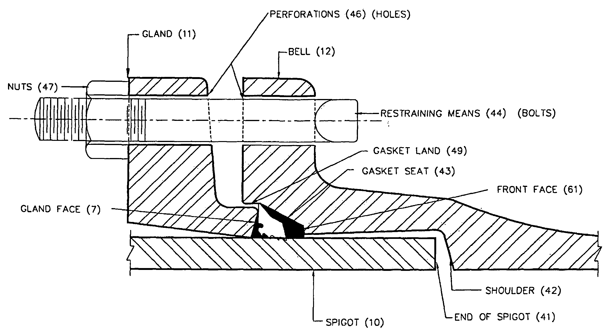
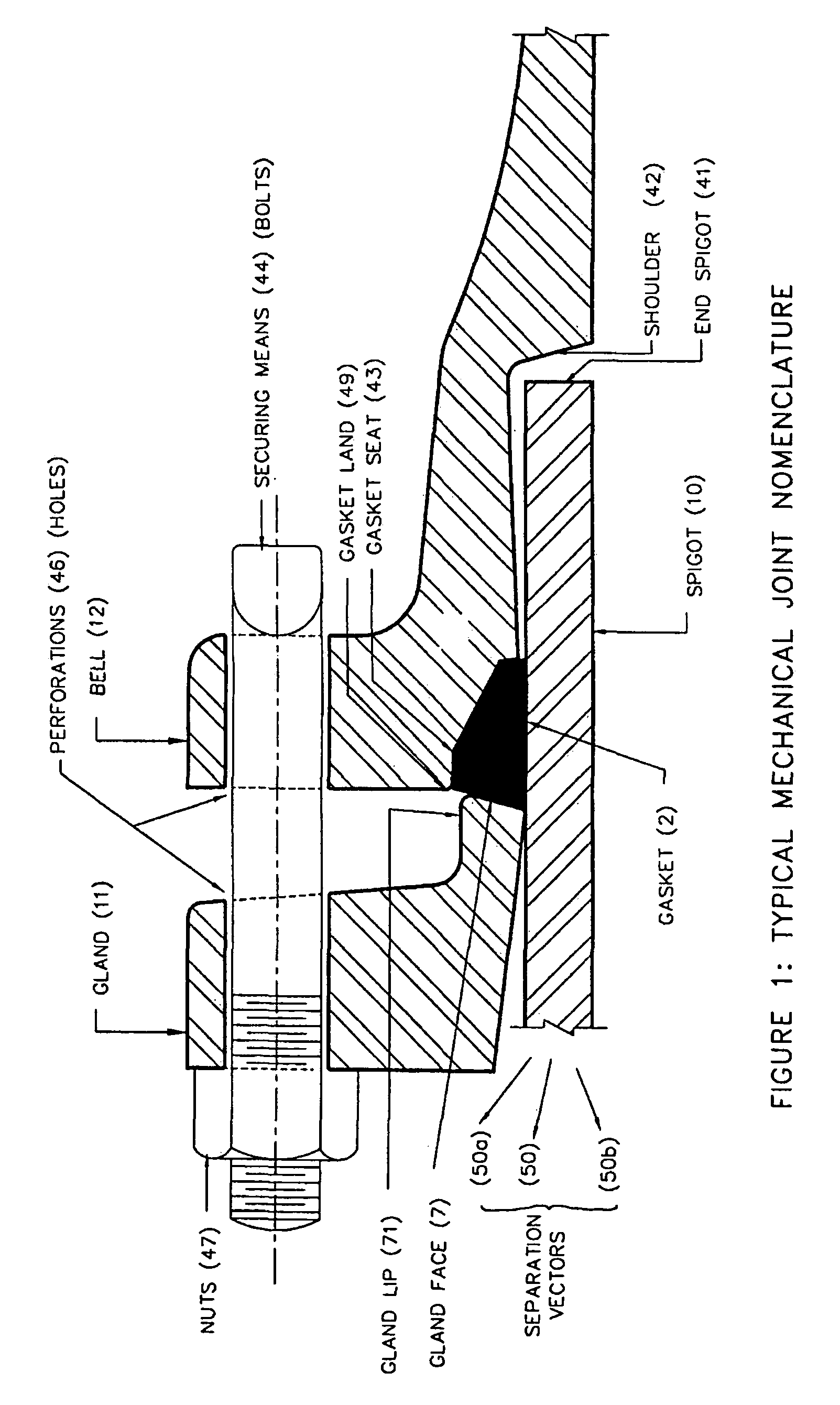
[0029] Turning now to the drawings, FIG. 1 presents a diagram of a typical mechanical joint. Assembly of the joint according to the current invention is practiced as known in the art. Particularly, but without limitation of the known variants which shall be as equally applicable to the present invention as they are to the known art, the joint contains the following elements in the following relationship. Compression ring or gland 11 is placed on spigot 10, following which gasket 2 is placed around the exterior of spigot 10. Spigot 10 is then adv...


PUM

PropertyMeasurementUnit
angleaaaaaaaaaa
angleaaaaaaaaaa
diameteraaaaaaaaaa

Abstract

The present invention may be basically described as a gasket for converting a standard mechanical joint into a restrained mechanical joint without the need for altered configuration of the bell, spigot, or gland of the joint, and without the need for additional fittings or devices. In the practice of the present invention, a standard mechanical joint's bell and gland configuration can be employed to connect a spigot end of one pipe length to the bell end of another pipe length in a restrained relationship, with the restraint based on forces superior to rubber-to-pipe friction. In more particular discussion of the embodiments taught, the invention includes forming the gasket to fit within the bell in such a manner that a void, or gutter, exists during rest, into which void the gasket compresses, which in turn influences the rotational motion of the segment. In this manner, the configuration of the gasket influences the timing and extent of rotation throughout the process of securing the gland to the bell.

Description

[0001] This is a continuation in part of currently co-pending application Ser. No. 09 / 590,586, to which this application claims priority and benefit, and which hereby is incorporated by reference.[0002] 1. Field of the Invention[0003] This invention relates generally to connections between lengths of pipe, or between pipes and fittings. More particularly, the invention is directed toward a device and method of connecting two lengths of pipe that maximizes the advantages of both restrained push-on joints as well as mechanical joints, as are known commonly in the art. The invention has application to long-run pipe lengths as well as fittings, appurtenances, and connections.[0004] 2. Description of Related Art[0005] Due to thrust forces, earth movement, and external mechanical forces exerted on pipes, the industry has focused substantial attention on the problem of maintaining connections between adjacent lengths of pipe after installation. The result of this attention is a library of ...

Claims


Application Information

Patent Timeline
Patent Type & Authority Applications(United States)
IPC IPC(8): F16L19/025F16L19/028F16L19/075F16L21/03
CPCF16L21/04Y10T29/49428F16L21/08
Inventor COPELAND, DANIEL A.
Owner US PIPE & FOUNDRY
Why Eureka
Try Eureka