Electronic camera and focus controlling method

a technology applied in the field of electronic cameras and focus control, can solve problems such as taking time to perform focus control

Inactive Publication Date: 2004-07-08
SANYO ELECTRIC CO LTD
View PDF15 Cites 20 Cited by
  • Summary
  • Abstract
  • Description
  • Claims
  • Application Information

AI Technical Summary

Problems solved by technology

However, if a so-called one shot autofocus control, in which the focus control is performed in response to a key operation for fetching the still image of the object, is adopted to the prior art, it may take time to perform the focus control when photographing a plurality of objects having the focal points adjacent to one another.

Method used


Image

  • Electronic camera and focus controlling method
  • Electronic camera and focus controlling method
  • Electronic camera and focus controlling method

Examples


Embodiment Construction

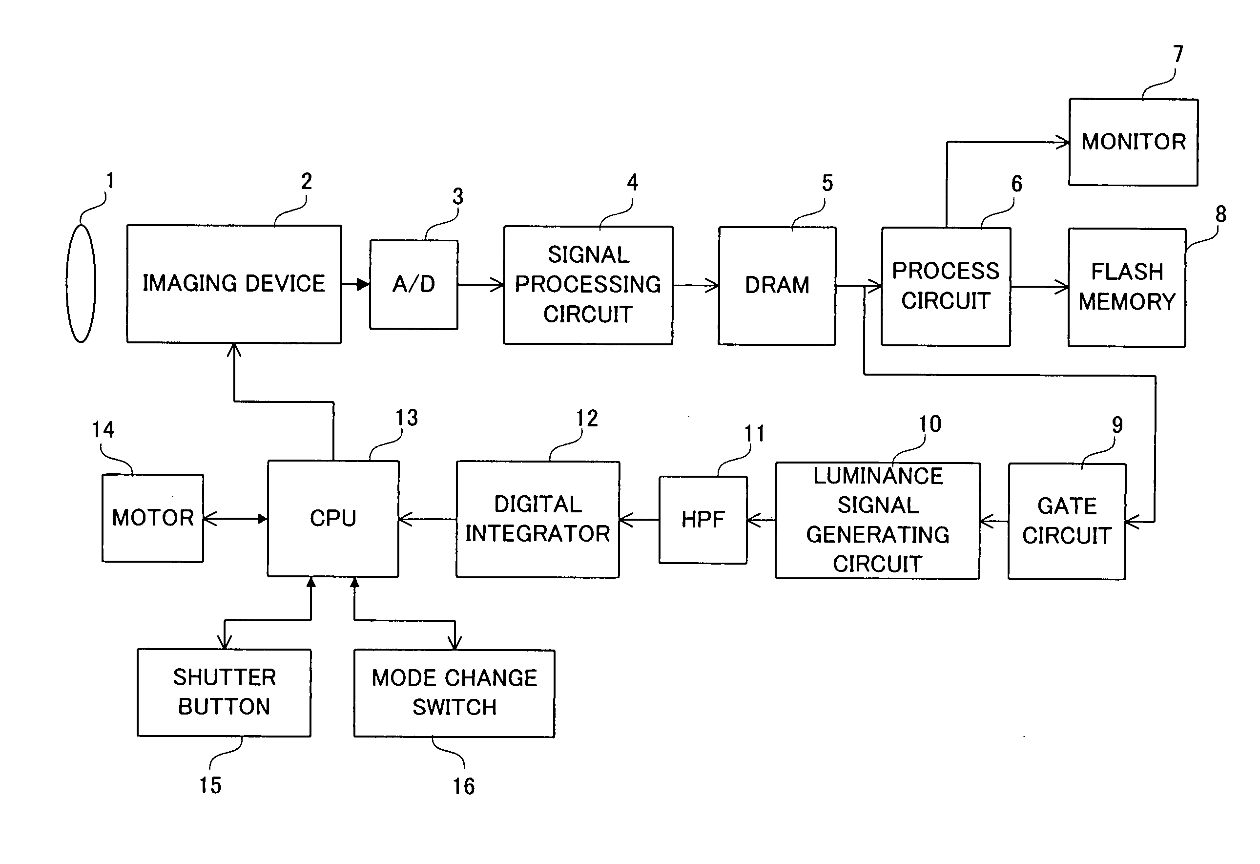
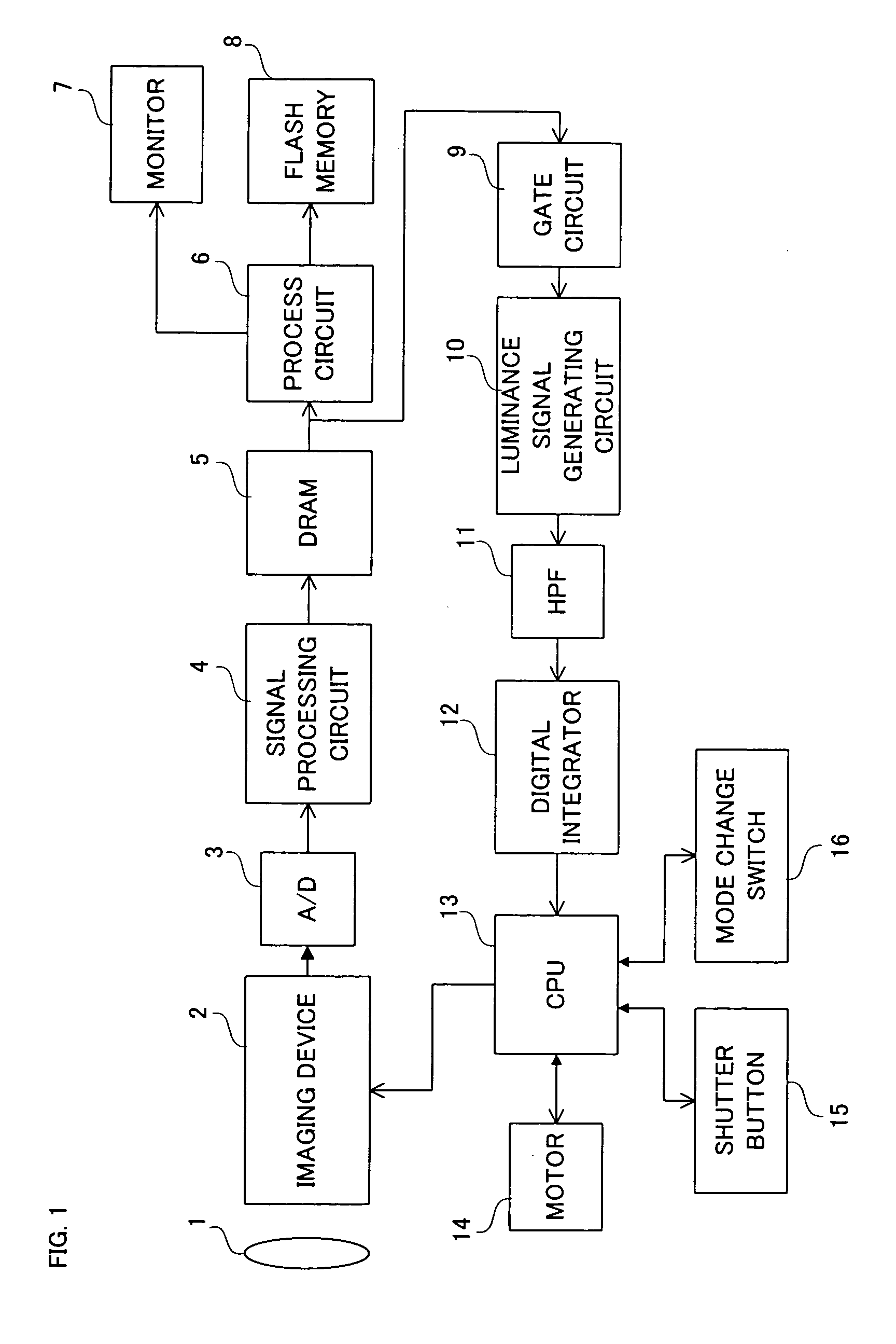
[0032] Referring to FIG. 1, an electronic camera of this embodiment includes a focus lens 1. An optical image of an object is incident upon a light-receiving surface of an imaging device (image sensor) 2 via the focus lens 1. On the light-receiving surface, a raw image signal corresponding to the optical image is generated by photoelectronic conversion.

[0033] If a camera mode is selected by a mode change switch 16, a CPU 13 instructs the imaging device 2 to output the raw image signal. The raw image signal converted photoelectronically on the light-receiving surface is outputted from the imaging device 2 by each 1 field. The outputted raw image signal of each field is converted into a digital signal by an AID converter 3 before being applied to a signal processing circuit 4.

[0034] The signal processing circuit 4 applies a well-known automatic exposure correction and an automatic white balance correction to the applied raw image signal. The exposure, in addition to applying a gain to...


PUM


Abstract

An electronic camera includes a shutter button. When the shutter button is half-depressed, a focal level of an object is determined on the basis of an image signal outputted from an imaging device, and a moving start position of a focus lens is settled on the basis of the determination result. More specifically, a correction amount of the moving start position is settled in accordance with the determination result of the focal level, and a position that subtracts the correction amount from a lens position at a time the shutter button being half-depressed is settled as the moving start position. The higher the focal level, the more reduced the correction amount. The focus lens gradually moves toward the imaging device from the settled moving start position, and a focal position is specified on the basis of the image signal outputted from the imaging device at each step.

Description

[0001] The present invention relates to an electronic camera and a focus control method. More specifically, the present invention relates to an electronic camera and a focus control method thereof that adjusts a distance, which is from a focus lens to an image sensor.PRIOR ART[0002] In a conventional electronic camera such as a video camera, a digital still camera, or the like, a focus is controlled on the basis of a high-frequency component of an image signal outputted from an imaging device (image sensor), taking advantage of a characteristic that the more exact the focus being brought to an object, the higher a contrast of an image of the object.[0003] Such the focus control method has a number of excellent advantages such as (1) no parallax in essence, (2) possible to focus a camera exactly even when a depth of field is shallow or the object is present in a far distance. In addition, this method does not need to prepare a special sensor for focus control extra, and is quite easy...

Claims


Application Information

Patent Timeline
Patent Type & Authority Applications(United States)
IPC IPC(8): G03B13/36G02B7/09G02B7/10G02B7/28G02B7/36G03B19/02H04N5/232
CPCH04N5/23212G03B13/36G02B7/38G02B7/365H04N23/673
Inventor KIKUCHI, KENICHISUGIMOTO, KAZUHIKO
Owner SANYO ELECTRIC CO LTD
Why Eureka
Try Eureka