Interlabial pad

a technology for the inner thighs and the outer thighs, which is applied in the field of inner thighs, can solve the problems of difficult to wear the inner thighs, and difficult to locate the right wearing point for the wearer

Inactive Publication Date: 2004-08-12
UNI CHARM CORP
View PDF6 Cites 12 Cited by
  • Summary
  • Abstract
  • Description
  • Claims
  • Application Information

AI Technical Summary

Problems solved by technology

However, compared to the sanitary napkin, the interlabial pad is more difficult to be worn than the sanitary napkin, because it is worn between the labia, which are difficult to be seen.
Moreover, if it is not fitted to an appropriate position, leakage damage tends to be considerable, because it is smaller than the sanitary napkin in size.
However, in such a structure, as the wearer feels for the wearing point with her nail tips, the wearer actually is obliged to wear it with her intuition so that it is not easy for the wearer to locate the right wearing point.
Especially, if the wearer has long nails or wears fake nails, it is extremely difficult to wear the aforementioned interlabial pad or the like of the prior art to the right position.
In addition, it is difficult to apply the interlabial pad into the labia with a satisfactory contact only by using the pinched projection 60.
Therefore, the aforementioned interlabial pad of the prior art does not come to facilitate the wearing by locating the right wearing point, reduce the occasion of mis-wearing or realize a satisfactorily close contact with the genital area.
Moreover, still menstrual blood or others may attach to finger tips during the wearing, constituting one of factors causing the reluctance of using the interlabial pad.
Consequently, in the aforementioned incontinence prevention pad, the fitting operation to a fingertip comes to be troublesome and burdensome.
As obvious from the foregoing, the finger hole provided on said incontinence prevention pad can not have a satisfactory effect of easy and rapid wearing, because the finger insertion direction is specified to make a right angle with the sheet surface.
In this respect, in case where the inner total circumference of the finger insertion opening is shorter than 30 mm, the finger insertion opening itself becomes small, and impedes finger insertion / extraction.
On the other hand, if it is longer than 120 mm, the interlabial pad is not fixed on the finger, preventing the ball of the finger from adhering securely to the sheet surface, and the wearing becomes troublesome.

Method used


Image

  • Interlabial pad
  • Interlabial pad
  • Interlabial pad

Examples


first embodiment

[0124] [First Embodiment]

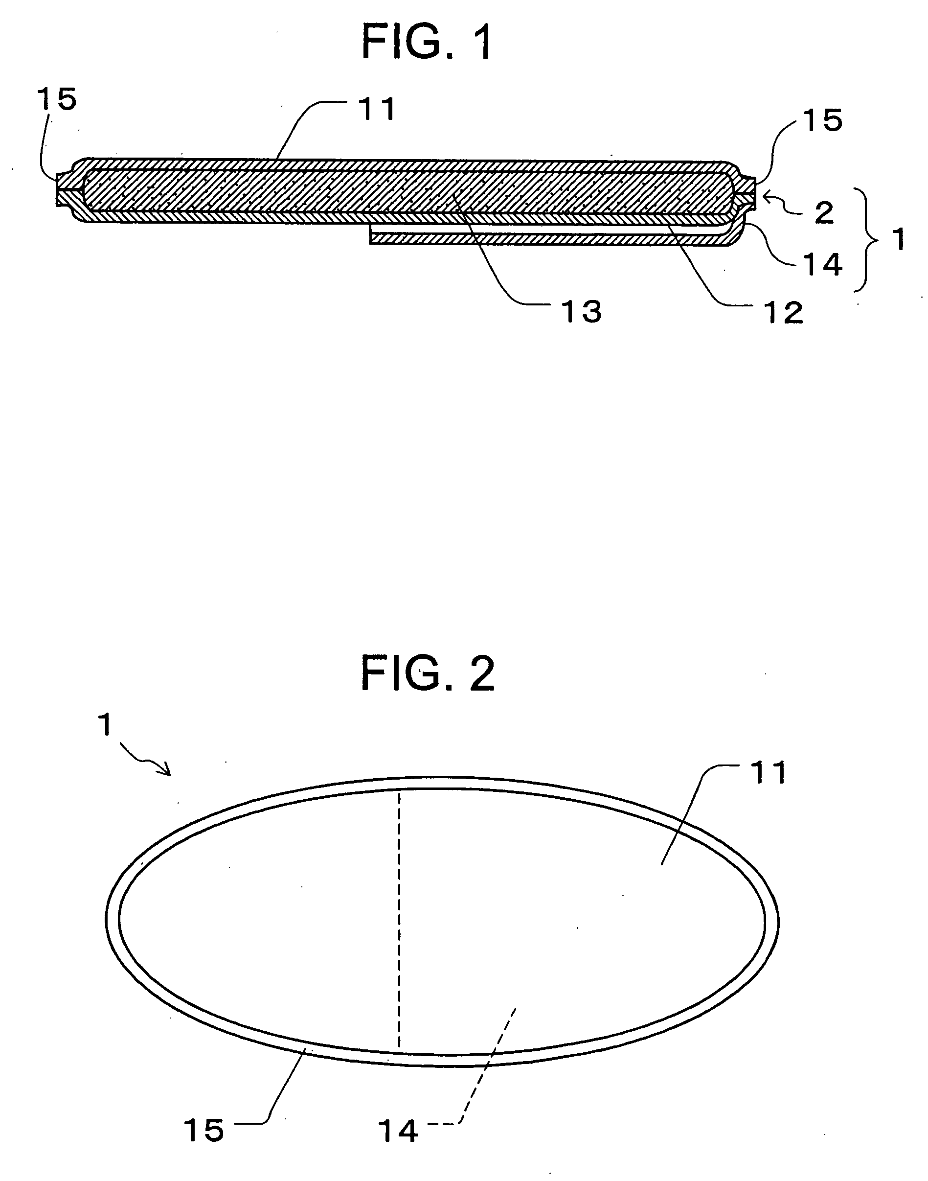
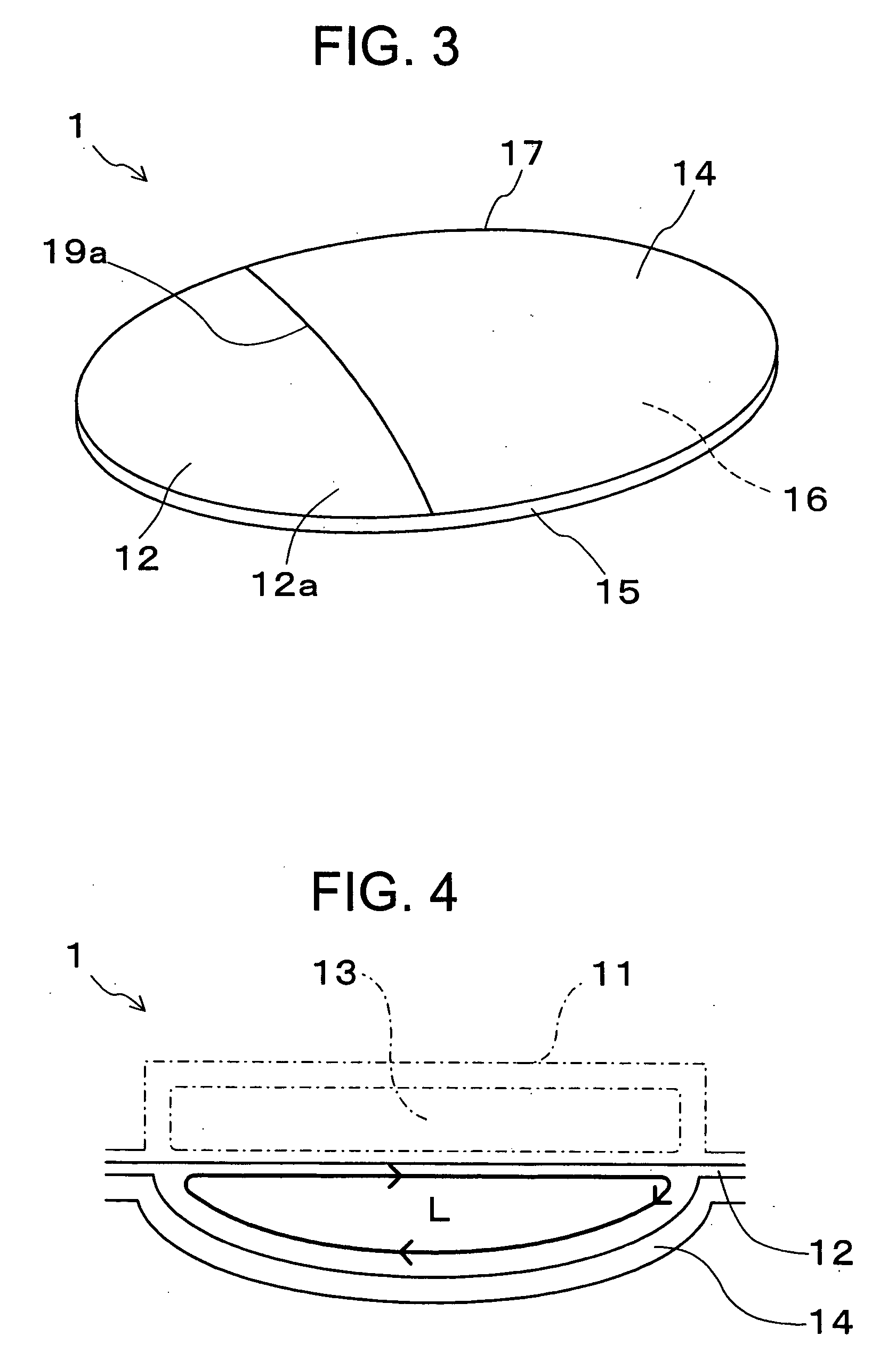
[0125] First, an interlabial pad where a pocket like mini sheet piece is attached on the opposite side face to the body side shall be described. FIG. 1 shows inner components of an interlabial pad 1 of the first embodiment, FIG. 2 and FIG. 3 show the appearance of the interlabial pad 1 of the first embodiment, and FIG. 4 is a partial cross section in the lateral direction of the interlabial pad 1 where a part of the interlabial pad 1 is cut off for illustrating concretely the "whole inner circumferential length of the finger insertion opening".

[0126]

[0127] The interlabial pad 1 of this embodiment comprises, as shown in FIG. 1, an absorbent layer 2 having a surface side sheet 11 (body side) made of water permeable material, a back side sheet 12 (the opposite side face to the body side) made of non water permeable material and an absorbent body 13, and a mini sheet piece 14 attached to the back side sheet 12.

[0128] The absorbent layer 2 is formed integrally b...

second embodiment

[0159] [Second Embodiment]

[0160] Now, an interlabial pad with flap a portion shall be described. FIG. 17 shows the opposite side face to the body side of an interlabial pad 20 with flap portions 24A and 24B; FIG. 18 shows a cross section along A-A of FIG. 17; FIG. 19 shows a state where the interlabial pad 20 is fitted on the fingertip; FIG. 20 shows components of the flap portions 24A and 24B of the interlabial pad 20; and FIG. 21 is a process diagram showing steps for forming the finger insertion opening 29a by bonding the flap portions 24A and 24B each other.

[0161] As shown in FIG. 17, the absorbent layer 25 has a lateral dimension and a longitudinal dimension and is substantially longer in the longitudinal dimension. Then, flap portions 24A and 24B are provided at both side edges of this absorbent layer 25, these flap portions 24A and 24B are folded toward the opposite side face to the body side 25b of the absorbent layer 25, and a superposition portion 26 where both are superpo...

third embodiment

[0179] [Third Embodiment]

[0180] Next, an interlabial pad having a long convex area protruding toward the body side in the body side face shall be described. FIG. 31 is a perspective view of an interlabial pad 30 having a long convex area 37.

[0181] As shown in FIG. 31, the interlabial pad 30 has a long convex area 37 on a surface side sheet 31 disposed on the body side face thereof. Besides, a mini sheet piece 34 is disposed on the opposite side face to the body side and the structure allows to insert a finger into a finger insertion pocket 36. Therefore, it becomes possible to locate exactly the position for introducing the long convex area 37 into the labia with the finger inserted into the pocket 36. Then, the adhesion between the interlabial pad 30 and the labia can further be enhanced, by introducing the long convex area 37 deep in the labia of the wearer, making possible to improve the advantage of the interlabial pad product, excellent adherence.

[0182] This long convex area 37...


PUM

PropertyMeasurementUnit
circumferential lengthaaaaaaaaaa

Abstract

The present invention concerns an interlabial pad easy to wear between the labia and provides an interlabial pad of a structure allowing to wear between the labia of a woman easily and appropriately. A mini sheet piece (14) is attached to the opposite side to the body side of the an interlabial pad (1) for constituting a pocket (16) for finger insertion and, at the same time, the shape of a finger insertion opening (19a) constituting the entrance of the pocket (16) is made flat in the planar direction of the sheet so that the boll of the finger can be inserted naturally in contact with the face of the sheet. In addition, the finger insertion opening (19a) is made to guide to a finger application point (3) appropriate for feeling for a wearing point in between the labia.

Description

[0001] This application is a Continuation of International Application No. PCT / JP02 / 04884 filed May 21, 2002, which application published in Japanese on Nov. 28, 2002 as WO 02 / 094148 A1 under PCT Article 21(2).[0002] 1. Technical Field[0003] The present invention relates to an interlabial pad that can be worn easily between labia.[0004] 2. Background Art[0005] Conventionally, a sanitary napkin and a tampon are used generally as a female sanitary product. Here, there have been great efforts to prevent the leak of menstrual blood from a gap caused by poor adhesion near the ostium vaginae as for the sanitary napkin. Moreover, as for the tampon, there have been great efforts for relieving a foreign feeling and discomfort when the sanitary product is worn and for lowering difficulty in intervaginal wearing due to the nature of the product.[0006] Under such situation, an interlabial pad have attracted people as a sanitary product positioned between the sanitary napkin and the tampon in re...

Claims


Application Information

Patent Timeline
Patent Type & Authority Applications(United States)
IPC IPC(8): A61F13/15A61F13/82A61F15/00
CPCA61F13/15211A61F2013/8497A61F13/15577A61F13/4702A61F13/4704A61F13/47209A61F13/474A61F13/534A61F13/535A61F13/55165A61F13/82A61F13/8405A61F15/001A61F2013/15235A61F2013/15357A61F2013/53445A61F13/15252A61F13/15
Inventor MIZUTANI, SATOSHIYAMAKI, KOICHINODA, YUKITOKUMOTO, MEGUMISAKAI, AKANE
Owner UNI CHARM CORP
Why Eureka
Try Eureka