Optical fiber management system and method and fiber bender thereof

a management system and optical fiber technology, applied in the field of optical fiber, can solve the problems of increasing the complexity of the modern computer and telecommunications network, the physical size of the connector, and the difficulty of service of the internal connection scheme,

Inactive Publication Date: 2004-08-26
CIENA
View PDF11 Cites 112 Cited by
  • Summary
  • Abstract
  • Description
  • Claims
  • Application Information

AI Technical Summary

Problems solved by technology

Modern computer and telecommunications networks are constantly growing more complex and have an ever-expanding need for bandwidth (the ability to accept, process, and / or transmit information).
One cannot merely increase the density on whim since optical fibers, however small they may be, do occupy space, and the housing or chassis in which they are disposed is finite in volume.
Internal connect schemes are difficult to service since the optical fibers were not easily disconnected from their respective optical transceivers.
Currently, one of the density limitations on a faceplate mounted cable interconnect scheme is the physical size of the connector.
Unfortunately, mounting small form factor transceivers on line module faceplates causes the fiber optic cable to enter the faceplate at an angle of incidence such that it becomes difficult to route the fiber away from the source and, at the same time, prevent the telecommunications equipment chassis doors from crushing the fiber optic cable when closed.
Additionally, as the density of the cables increases, it becomes increasingly difficult for technicians to service the equipment without disrupting cables adjacent to the cables that need to be serviced.
These boots can be rotated slightly but will interfere with adjacent boots when the angle becomes too great.
However, it has several problems associated with it.
First, it is completely incompatible with LC connectors that do not have specific Siecor boots attached thereon.
Second, it does not actually cover a significant amount of the cable; as a result, even though the cable is kept fairly rigid, the clip does not actually protect the fiber optic cable.
A sharp blow by either the door of the chassis of a networking device or by an incautious technician can still damage the optical fiber cable.
Finally, there is no way to tell precisely where on the optical fiber this device is supposed to be placed for optimal bending.
The Corning clip fails to support the bent portion of the fiber throughout the entire section of bent fiber.
As such, the fiber may not lay properly in the Corning clip.
Also, the Corning clip appears to be less than reliable when used with smaller width optical fibers.
These stiffening ribs increase the size of the fiber bender; as a result, adjacent fibers connected to the same LC connector (which typically accommodates two fibers very close together) are pushed apart, causing undue stress on the connector and thus the transceiver.
Other companies utilize external faceplate interconnect schemes which cannot utilize the current industry solutions.

Method used


Image

  • Optical fiber management system and method and fiber bender thereof
  • Optical fiber management system and method and fiber bender thereof
  • Optical fiber management system and method and fiber bender thereof

Examples


Embodiment Construction

[0029] Description will now be given of the invention with reference to FIGS. 1-5E. It should be noted that the figures are exemplary in nature and are meant in no way to limit the scope of the invention.

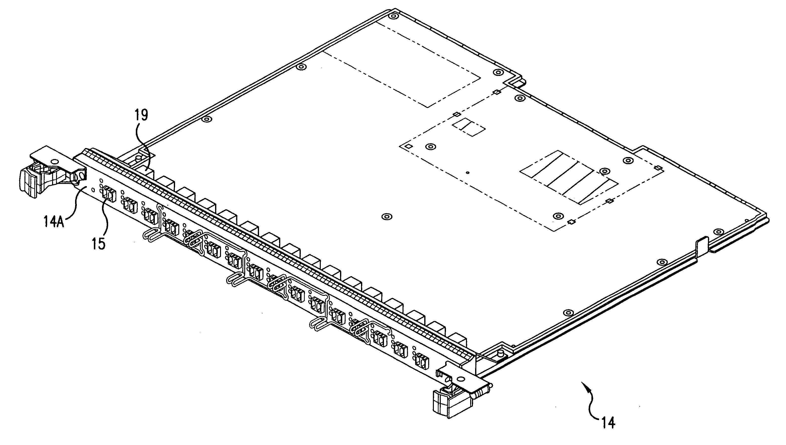
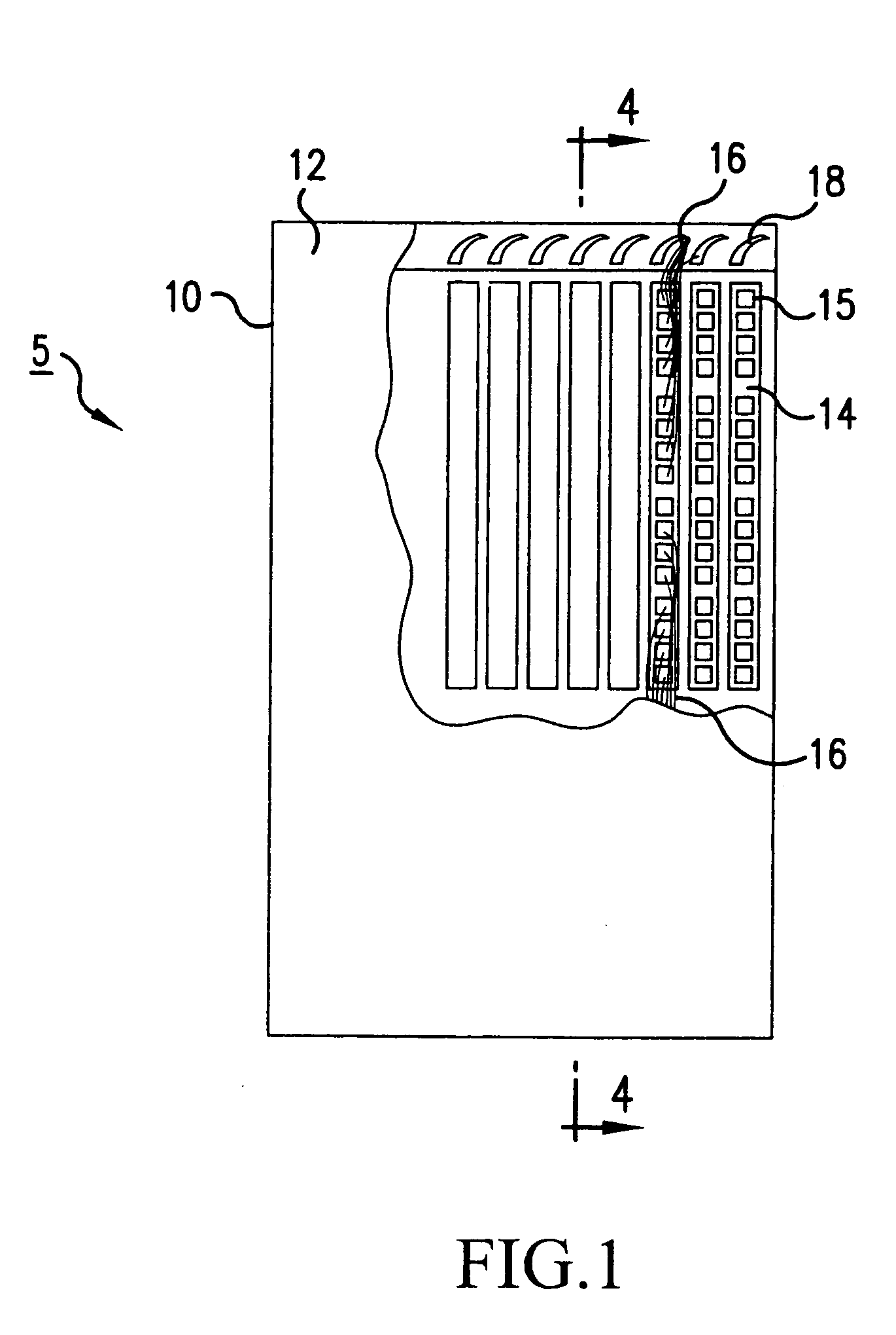
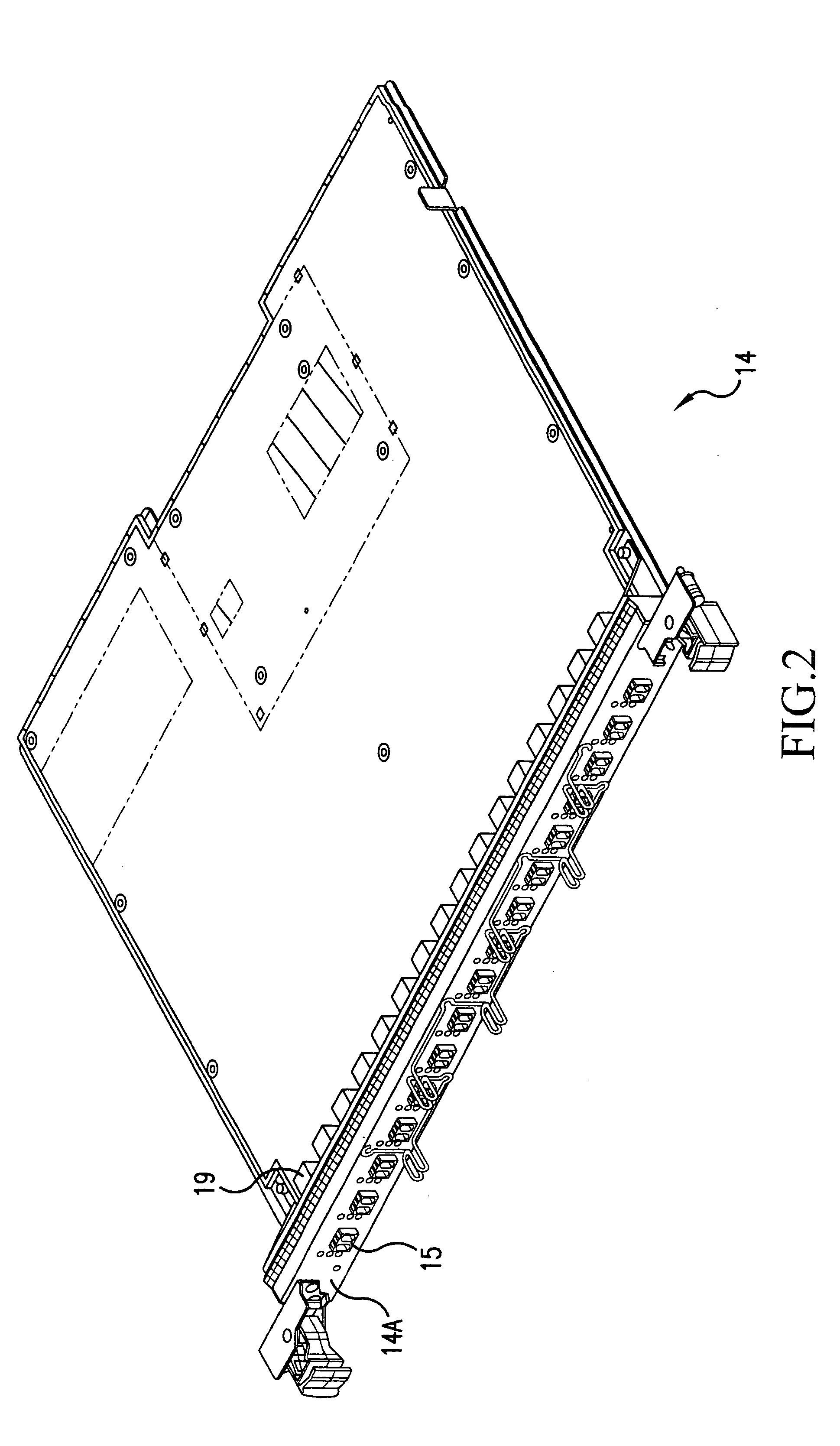
[0030] FIG. 1 depicts a schematic of a typical telecommunications networking device 5 usable in an optical network. Device 5 includes a chassis 10 which has an openable door 12 shown in broken view. Within the chassis is disposed some support structure (not shown) such as shelving, hooks, etc., for supporting a series of circuit boards or line modules 14. Previously, line modules were provided with eight optical transceivers each with their respective optical fibers being mounted internal to the faceplate of the line module (such a device is known as an LM-8). With the advent of the less bulky small form factor transceivers described above, the new standard of line modules is now being provided with sixteen optical transceivers (or an LM-16) in a faceplate mounted external interconn...


PUM


Abstract

A fiber bending apparatus for bending an optical fiber in a networking device and an optical fiber management system and method are provided. The fiber bender has an arcuate main body which is attached to the end of an optical fiber above the male connector and partially including the connector boot, bending the fiber substantially orthogonal to a direction from which the fiber is connected to a line module of the networking device, i.e., substantially parallel to the faceplate of the line module. In this way, the optical fibers are made to bend away from the chassis of the networking device, thereby preventing them from being crushed when the door of the chassis is closed. The optical fibers are also shielded from inadvertent impacts when a technician is working on the networking device. By enabling the optical fibers to be easily directed and managed, the overall fiber density of the networking device may be increased, thereby increasing its bandwidth and information processing capabilities.

Description

[0001] This application is a Divisional of co-pending Application Ser. No. 09 / 916,980 filed on Jul. 27, 2001, the entire contents of which are hereby incorporated by reference and for which priority is claimed under 35 U.S.C. .sctn. 120.[0002] 1. Field of the Invention[0003] The invention relates to devices which employ optical fiber; more specifically, the invention relates to a device, system, and method of managing optical fibers in a way to keep them neat and protected from harm.[0004] 2. Description of Related Art[0005] Modern computer and telecommunications networks are constantly growing more complex and have an ever-expanding need for bandwidth (the ability to accept, process, and / or transmit information). Many of the components used in such networks utilize optical transceivers and optical fibers as the means of communicating among and within the various components.[0006] One of the ways that optical network components can be made more efficient is by providing them with a ...

Claims


Application Information

Patent Timeline
Patent Type & Authority Applications(United States)
IPC IPC(8): G02B6/44
CPCG02B6/4478G02B6/4452
Inventor ERWIN, CHARLES MATTHEWGEHRKE, GARY CURTISPARASNIS, NARASINHA CHANDRAKANT
Owner CIENA
Why Eureka
Try Eureka