Mounting structure and method for heat accumulation tank

a technology for mounting structures and heat accumulation tanks, which is applied in the direction of rigid containers, machines/engines, packaging, etc., can solve the problems of weak holding strength of the mounting structure for a heat accumulation tank described in jp-a-10-86644, difficult to apply surface pressure evenly, and easy damage to the main body of the tank

Inactive Publication Date: 2004-11-18
TOYOTA JIDOSHA KK +1
View PDF51 Cites 1 Cited by
  • Summary
  • Abstract
  • Description
  • Claims
  • Application Information

AI Technical Summary

Problems solved by technology

However, the holding strength of the mounting structure for a heat accumulation tank described in JP-A-10-86644 is weak because only a portion of the heat accumulation tank is held in the circumferential direction.
Further, it is difficult to apply the surface pressure evenly because the tank main body is directly supported by the bracket.
This results in problems, such as that it makes the tank main body susceptible to damage.
Also, if the bracket, which should reliably hold the tank main body, is spot welded to the outer tank of the tank main body, a slow leak may develop across the interface of the spot weld over an extended period of time.
This slow leak reduces the degree of vacuum between the inner and outer tanks, which may result in a decrease in heat retaining performance.

Method used


Image

  • Mounting structure and method for heat accumulation tank
  • Mounting structure and method for heat accumulation tank
  • Mounting structure and method for heat accumulation tank

Examples


Embodiment Construction

[0020] In the following description and the accompanying drawings, the present invention will be described in more detail in terms of exemplary embodiments.

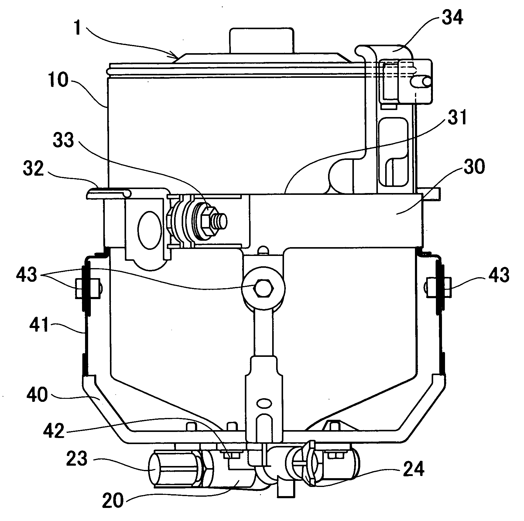
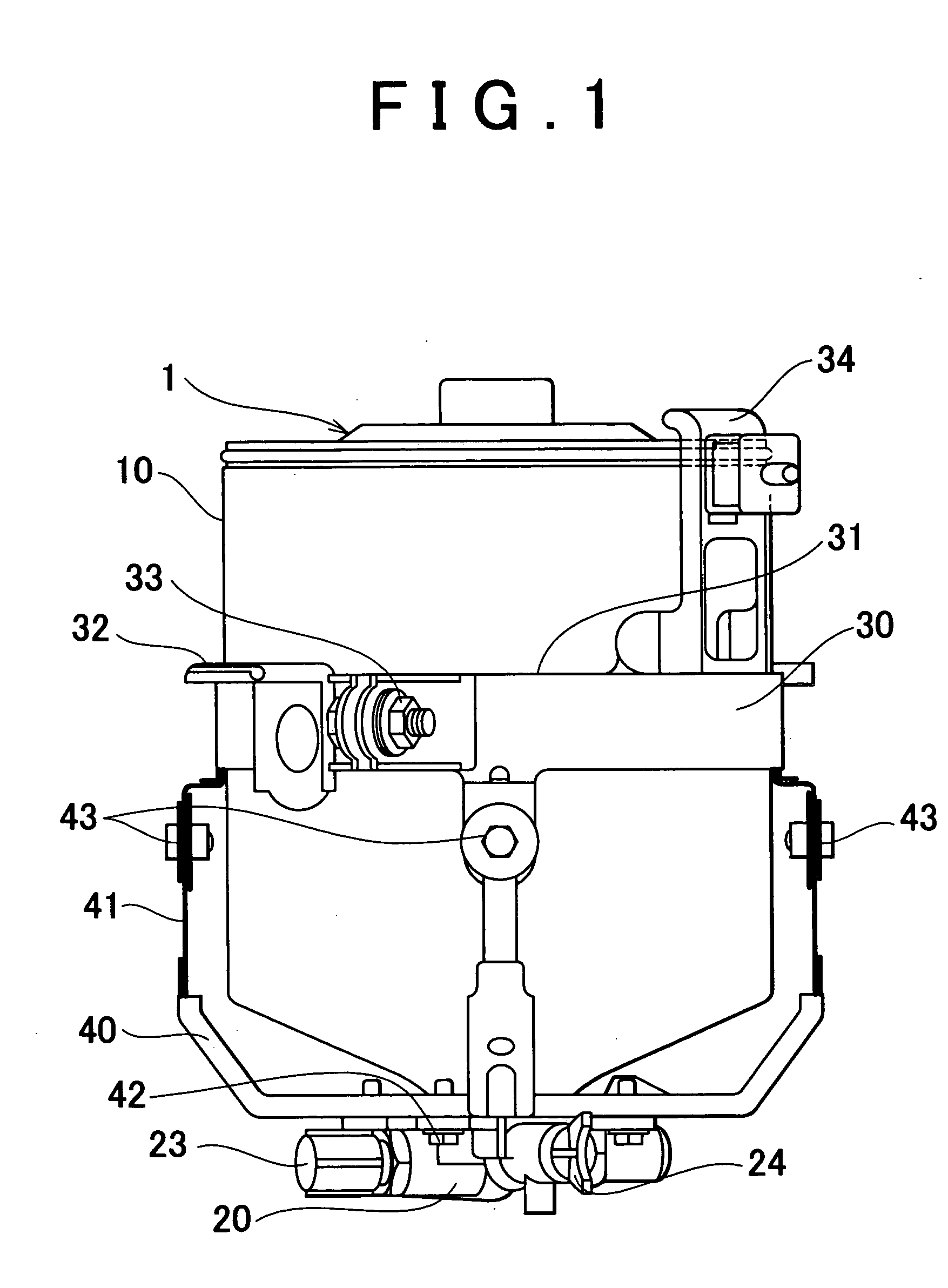
[0021] A heat accumulation tank 1 to which a mounting structure for a heat accumulation tank according to one exemplary embodiment of the invention can be applied will be described with reference to FIGS. 1 and 9.

[0022] As shown in FIGS. 1 and 9, the heat accumulation tank 1 has a tank main body 10 which stores fluid (coolant) while keeping it warm. The heat accumulation tank 1 also has a housing 20 in which is provided a fluid passage that opens into an inner portion of the tank main body 10, and through which fluid flows. The tank main body 10 has a tank main body opening 13 into which the housing 20 is inserted. The heat accumulation tank 1 has an axial core, and is mounted to a receiving member of a vehicle with an orientation such that the axial core is substantially vertically. In the example shown in the drawing, the heat ...


PUM


Abstract

A mounting structure for a heat accumulation tank is provided with an elastic member that wraps around a tank main body, and a heat accumulation tank mounting member which wraps around the outer peripheral surface of the elastic member and holds the tank main body by being tightened in the circumferential direction, and which attaches to a receiving member. The elastic member is a molded part. The length of the elastic member is shorter than length of the circumference of the outer peripheral surface of the tank main body. The heat accumulation tank mounting member includes a shift inhibiting portion which inhibits an upward shift of the tank main body. The outside diameter of the tank main body becomes increasingly wider in the upward direction.

Description

INCORPORATION BY REFERENCE[0001] The disclosure of Japanese Patent Application No. 2003-093015 filed on Mar. 31, 2003, including the specification, drawings and abstract is incorporated herein by reference in its entirety.[0002] 1. Field of the Invention[0003] The invention relates to a mounting structure and method for mounting a heat accumulation tank to receiving member.[0004] 2. Description of the Related Art[0005] JP-A-2002-188442 and JP-A-2000-73764 disclose proposals for a heat accumulation tank. This heat accumulation tank includes a tank main body which stores, while keeping warm, coolant for an internal combustion engine. The tank main body has an inner tank and an outer tank, with a space therebetween which is substantially a vacuum in order to improve heat retention. Also as related art, JP-A-10-86644 discloses a mounting structure for mounting a heat accumulation tank to a receiving member (such as a vehicle body member). More specifically, the publication discloses a m...

Claims


Application Information

Patent Timeline
Patent Type & Authority Applications(United States)
IPC IPC(8): F01P3/20B60H1/08F01P11/20F02N19/10
CPCF01P11/20F01P2011/205F02N19/10
Inventor YOSHIKAWA, SHIGETAKASHINPO, YOSHIKAZUARISAWA, KATUHIKOGOTO, ISAOIINUMA, MASAAKIMORIKAWA, TOSHIOTOYOSHIMA, TAKASHIMIYATA, YOSHIO
Owner TOYOTA JIDOSHA KK
Why Eureka
Try Eureka