
Base and electrical outlet having an expandable base mounting aperture and method for making same

a technology of expanding base and mounting aperture, which is applied in the direction of electrical apparatus casing/cabinet/drawer details, coupling device connections, casings/cabinets/drawers, etc., can solve the problem that the amount of work required for the installation of electrical outlet bases becomes very significant, and achieves the effect of reducing the amount of time needed and saving further time and expens

Inactive Publication Date: 2005-01-06
HUBBELL INC
View PDF33 Cites 20 Cited by
  • Summary
  • Abstract
  • Description
  • Claims
  • Application Information

AI Technical Summary

Benefits of technology

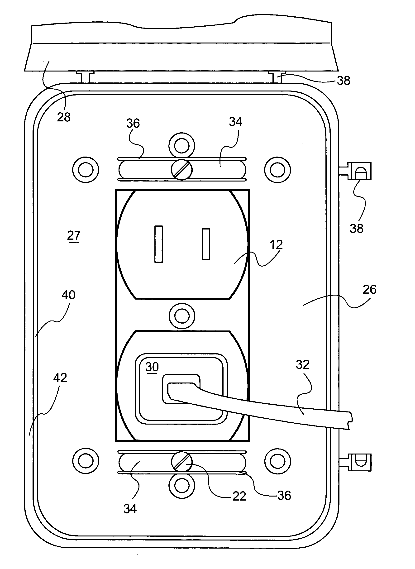
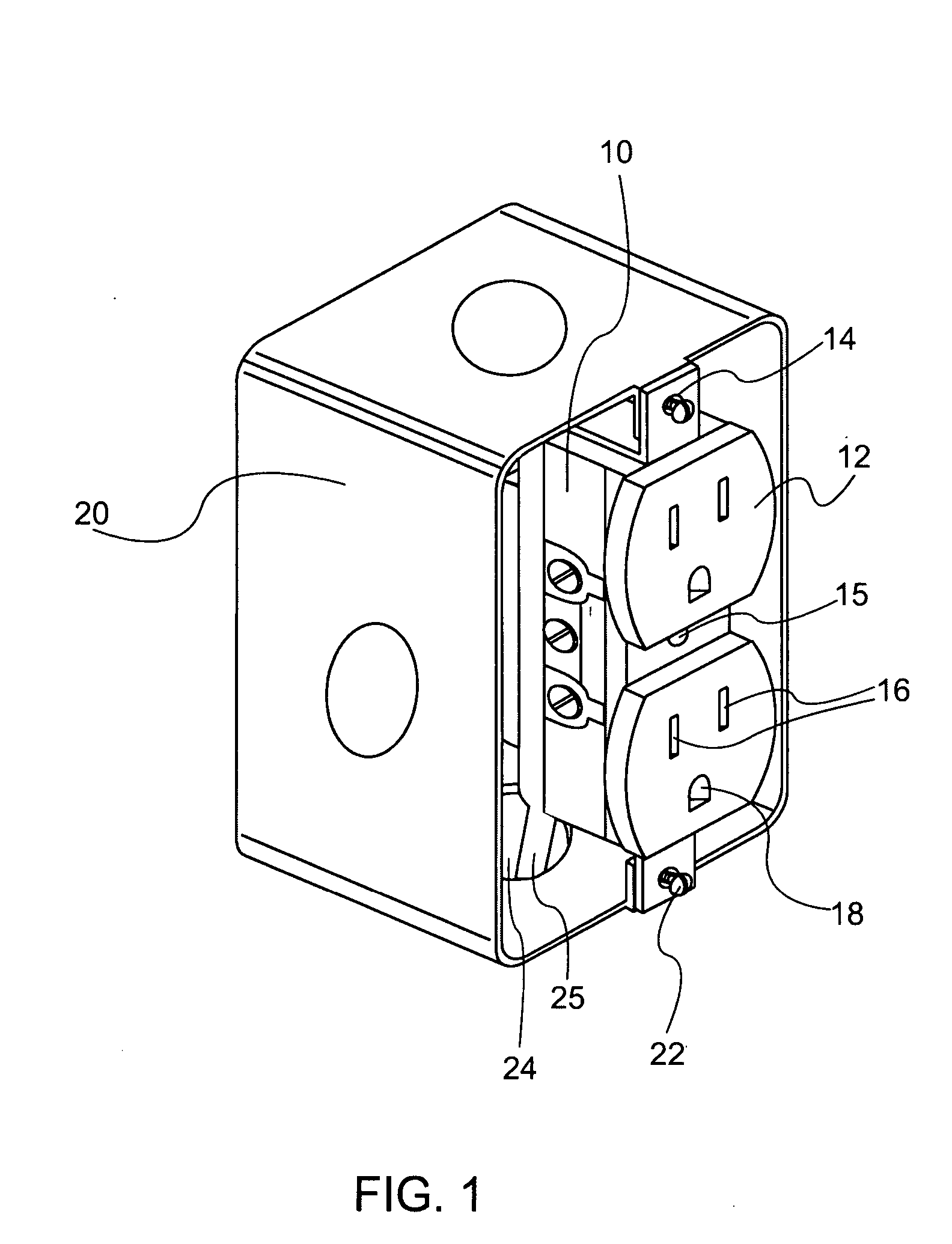
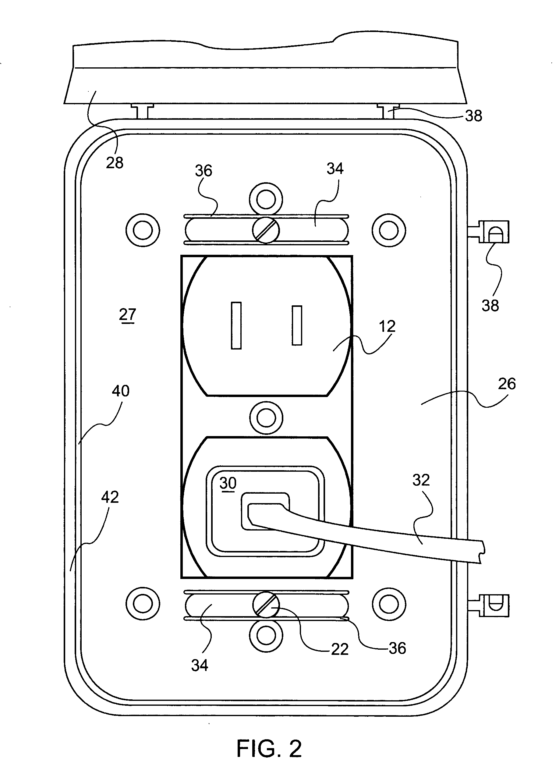
The present invention provides a base for an electrical outlet cover that can be easily mounted without removing the existing mounting screws that serve to fix an electrical outlet to an electrical box. The base has a flexible portion adjacent to the mounting aperture, which allows the base to expand and receive the fastening device, and then return to its relaxed state where it no longer permits the passage of the fastening device. The base is designed to fit neatly over the outlet and can be easily installed or replaced. The technical effect of this invention is to save time and expense by eliminating the need to remove the existing mounting screws and using them as the fastening device for the base.

Problems solved by technology

When a large number of outlet cover bases are to be installed, as in a new home or commercial building, the amount of work required for the installation of electrical outlet bases becomes very significant indeed.

Method used


Image

  • Base and electrical outlet having an expandable base mounting aperture and method for making same
  • Base and electrical outlet having an expandable base mounting aperture and method for making same
  • Base and electrical outlet having an expandable base mounting aperture and method for making same

Examples


Embodiment Construction

[0019] According to the present invention a base for an electrical outlet cover is provided wherein a backing member has at least one socket aperture and at least one base mounting aperture. In one embodiment, at least a portion of the backing member adjacent to the base mounting aperture is flexible, enabling the base mounting aperture, upon the application of pressure to the backing member, to expand and receive a fastening device. When the application of pressure is discontinued the base mounting aperture returns to its relaxed state wherein it no longer permits the passage of the fastening device. Typically the fastening device will be a screw and the backing member will have two socket apertures that fit over and provide access to two outlet sockets. The backing member also will commonly have two base mounting apertures centered on or near the longitudinal axis of the backing member and positioned in the backing member so as to line up with corresponding outlet mounting apertur...


PUM


Abstract

A base for an electrical outlet cover, an electrical outlet, and manufacturing method, the base including a backing member containing various mounting apertures designed to permit the passage of fastening devices, other apertures to allow access to portions of the electrical outlet, and sidewalls adapted to support and strengthen the base and to provide a place of attachment for hinges to which a cover may be attached. At least a portion of the backing member adjacent to a mounting aperture is flexible, whereby upon the application of pressure the mounting aperture can expand to receive a screw head therethrough and upon the release or discontinuation of such pressure the mounting aperture can return to its relaxed state, thus allowing the base to be installed over an existing electrical outlet without the need to remove any mounting screws. An alternate embodiment includes a base mounting aperture backed by a retaining device. The retaining device is sized so as to permit the passage of the body but not the head of a fastening device. Access to the fastening device is obtained by inserting a screwdriver or other tool through the base mounting aperture.

Description

BACKGROUND OF THE INVENTION [0001] 1. Technical Field [0002] This application is a continuation of U.S. application Ser. No. 10 / 409,442, filed on Apr. 1, 2003 entitled “Base and Electrical Outlet Having an Expandable Base Mounting Aperture and Method for Making Same”, which is a continuation of U.S. application Ser. No. 10 / 157,289, filed on May 28, 2002, entitled “Base and Electrical Outlet Having an Expandable Base Mounting Aperture and Method for Making Same”, which is a continuation of U.S. application Ser. No. 09 / 772,737, filed on Jan. 30, 2001, entitled “Base and Electrical Outlet Having an Expandable Base Mounting Aperture and Method for Making Same”. This invention generally relates to covers for electrical outlets, and more specifically relates to a base for such a cover, an electrical outlet, and related method of manufacture. [0003] 2. Background Art [0004] Electrical outlets in both home and commercial settings typically include a receptacle containing one or more sockets...

Claims


Application Information

Patent Timeline
Patent Type & Authority Applications(United States)
IPC IPC(8): H02G3/14H02G3/18
CPCH02G3/18H02G3/14
Inventor SHOTEY, MICHAEL J.SHOTEY, MARCUS J.MALTBY, EDGAR W.
Owner HUBBELL INC
Learn More