Lamp control system

a control system and lamp technology, applied in the direction of electric variable regulation, process and machine control, instruments, etc., can solve the problems of lamp not being able to lamp cannot be turned on using the lamp switch,

Inactive Publication Date: 2005-01-06
LOGAN JAMES D
View PDF7 Cites 13 Cited by
  • Summary
  • Abstract
  • Description
  • Claims
  • Application Information

AI Technical Summary

Benefits of technology

[0013] These and other objects, features and advantages of the invention will be more clearly understood by considering the following detailed description of a preferred embodiment of the invention. In the course of this description, frequent reference will be made to the attached drawings.

Problems solved by technology

As a result, when the person leaves and later re-enters the room after dark, an attempt to turn on the lamp at the wall switch fails.
Also, if the wall switch is turned off, the lamp cannot be turned on using the lamp switch.
Thus, at nighttime when the room is reentered, the wall switch can't be used to turn the lamp on again.

Method used


Image

  • Lamp control system
  • Lamp control system
  • Lamp control system

Examples


Embodiment Construction

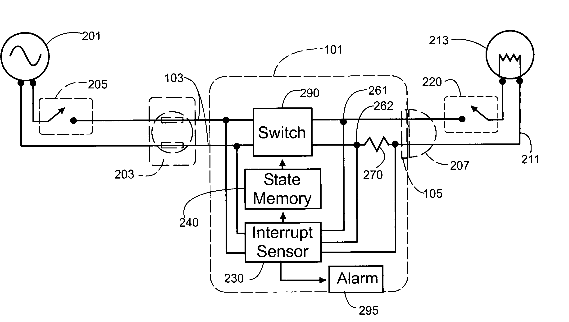
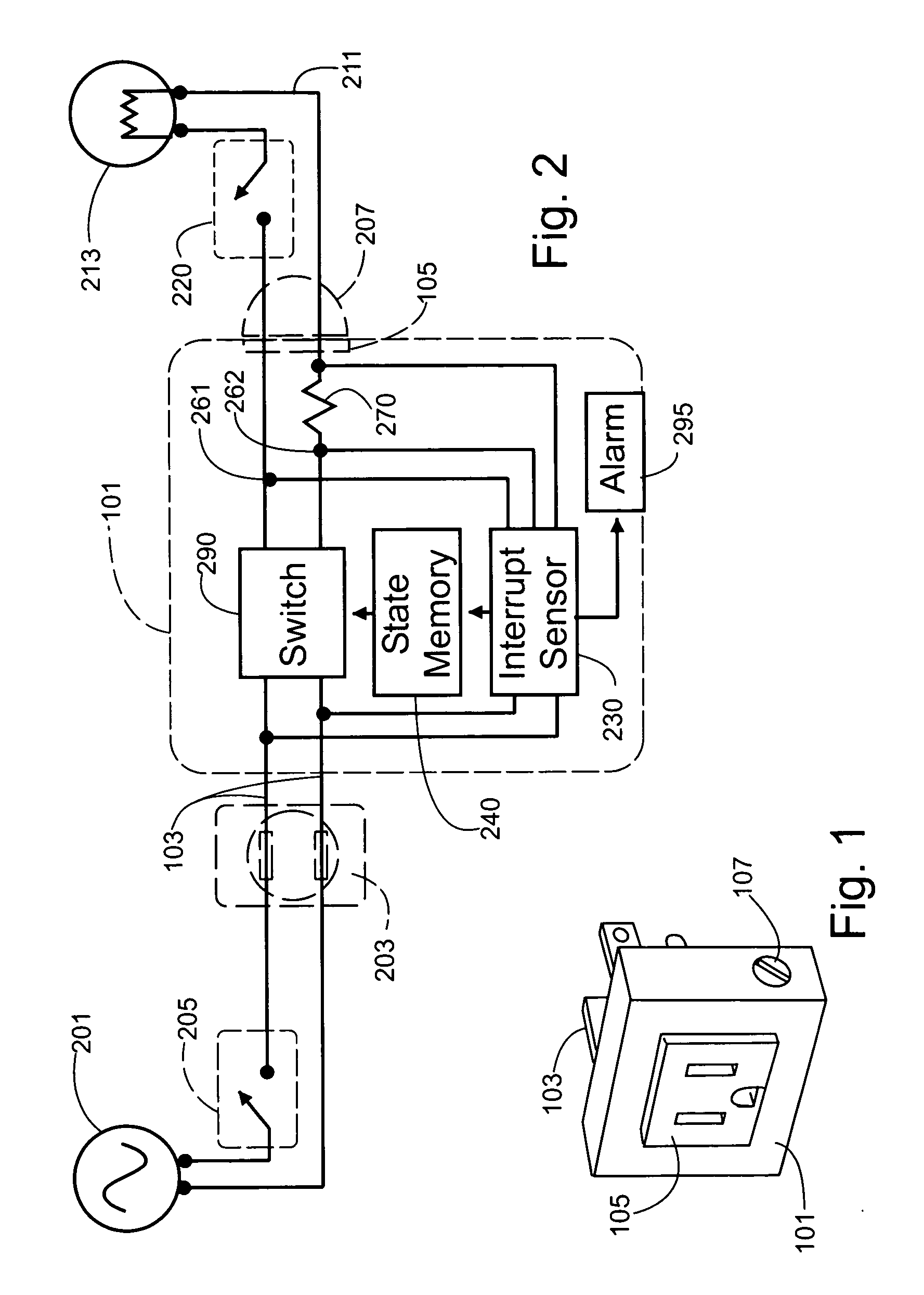
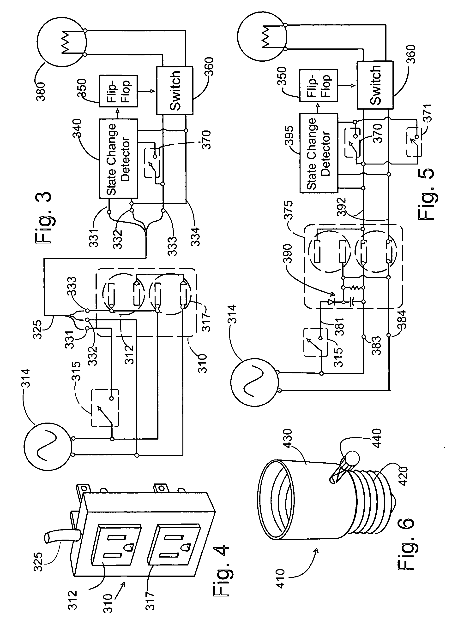
[0020] One preferred embodiment of the invention takes the form of a control adapter that plugs into a conventional switched electrical outlet and into which includes a female power socket into which the power cord of conventional lamp is plugged. This control adapter monitors the output voltage level delivered by the switched outlet and monitors the impedance presented by the switched lamp load. The control adapter includes a two-state controllable switch, which in turn controls the flow of electrical energy to the connected lamp. A momentary interruption in outlet supply voltage (created by toggling the wall switch OFF momentarily) is interpreted as a state change command, which changes the ON / OFF state of the controllable switch. Similarly, a momentary increase in the impedance presented by the switched lamp when the switch at the lamp is momentarily turned OFF also changes the ON / OFF state of the controllable switch. When the controllable switch is in the ON state, momentarily t...


PUM


Abstract

A control circuit for operating a lamp or other electrically operated device using a conventional wall socket outlet that is selectively energized under the control of a conventional wall mounted switch. To permit the lamp to be independently controlled using either the wall switch or the lamp switch, a wall adapter unit is employed that plugs into the wall outlet and into which the lamp's power cord is plugged. Sensing means are employed to detect the operation of either the wall switch or the lamp switch to control an electrically operated switch which turns the lamp ON and OFF whenever either the wall switch or the lamp switch are operated. Different embodiments are provided for use with conventional electrical wiring and with either a conventional lamp or lamp incorporating additional circuitry to adapt it for use with the wall socket adapter.

Description

CROSS REFERENCE TO RELATED APPLICATIONS [0001] This application is a division of, and claims the benefit of the filing date of, U.S. patent application Ser. No. 10 / 160,859 filed on May 31, 2002 which was a non-provisional of U.S. Provisional patent application Ser. No. 60 / 295,468 filed on Jun. 1, 2001, which was published as U.S. patent application Publication 2002 / 0180367 A1 on Dec. 5, 2002 and which will issue on Mar. 23, 2004 as U.S. Pat. No. 6,710,553.FIELD OF THE INVENTION [0002] This invention relates to electrical power supply control circuitry and more particularly to a control for controlling a lamp or other electrical device using either the device's ON / OFF switch or a remote wall switch which controls the energization of a conventional electrical outlet which supplies power to the device. BACKGROUND OF THE INVENTION [0003] In household electrical systems, it is common to supply a wall outlet with electrical power through a wall switch positioned near an entryway. A lamp m...

Claims


Application Information

Patent Timeline
Patent Type & Authority Applications(United States)
IPC IPC(8): H05B37/02
CPCH05B37/0209H05B47/165H05B47/17
Inventor LOGAN, JAMES D.
Owner LOGAN JAMES D
Why Eureka
Try Eureka