Progressing cavity pump/motor

a cavity pump and motor technology, applied in the direction of positive displacement liquid engines, liquid fuel engines, rod connections, etc., can solve the problems of difficult direct alignment of the motor/pump rotor section, difficult transportation and handling of the rotor,

Active Publication Date: 2012-04-03
ROBBINS & MYERS ENERGY SYST
View PDF8 Cites 11 Cited by
  • Summary
  • Abstract
  • Description
  • Claims
  • Application Information

AI Technical Summary

Problems solved by technology

In some applications, a progressing cavity pump has an extremely long length, e.g., thirty feet or more, which makes transportation and handling of the rotor difficult.
Such direct alignment of a motor / pump rotor section is difficult to envision in the field or a well site.

Method used


Image

  • Progressing cavity pump/motor
  • Progressing cavity pump/motor
  • Progressing cavity pump/motor

Examples


Embodiment Construction

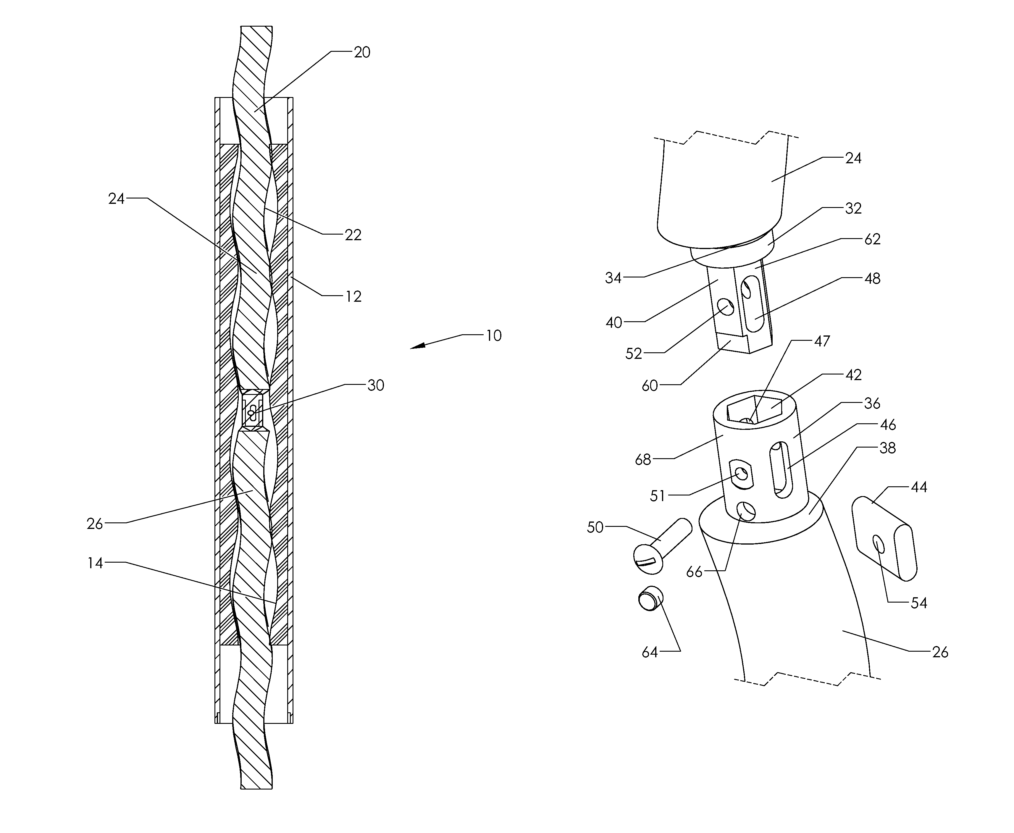
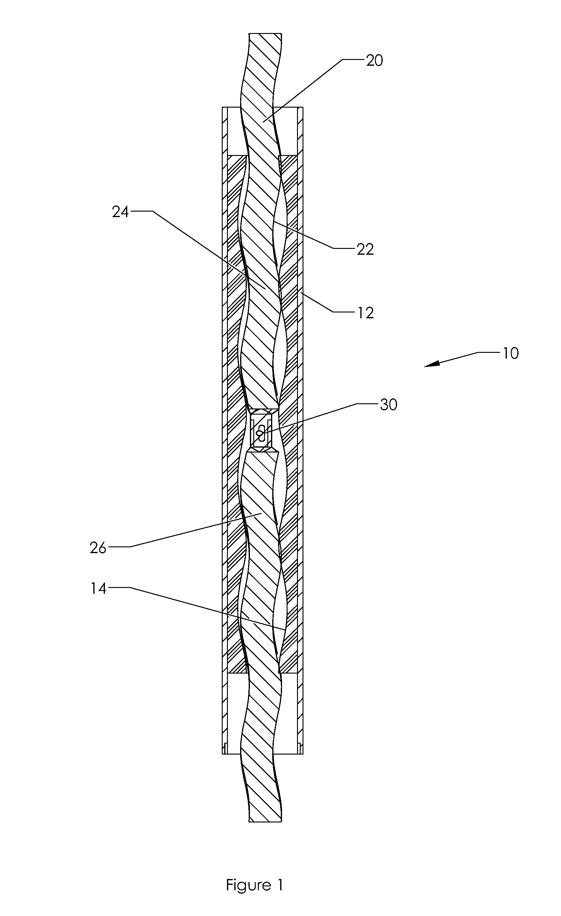
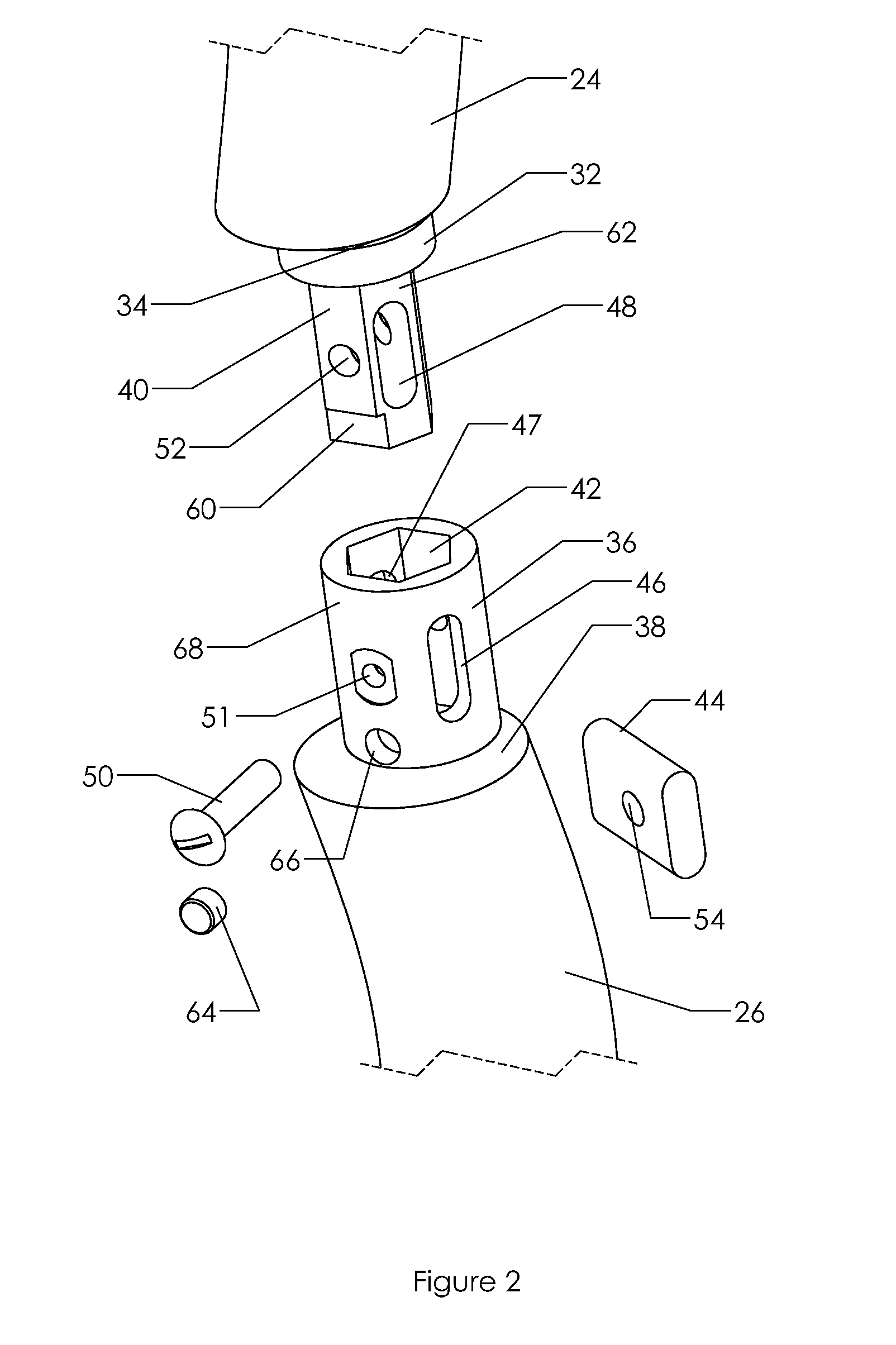
[0011]FIG. 1 is a cross-sectional view of a progressing cavity pump / motor 10, which is positionable along a tubular string in a well to either pump fluids to the surface through the tubular string or to create downhole mechanical energy from fluid transmitted downhole to the pump / motor, e.g., to rotate a bit. The pump / motor 10 includes a stator tube 12 having a contoured interior surface 14 along an axial length thereof. The rotor 20 extends axially within the stator tube and, as shown in FIG. 1, frequently extends vertically above the upper end of the stator tube, and below a lower end of the stator tube. Rotor 20 has an exterior contoured surface 22 creating progressing cavities between the contoured interior surface and the contoured exterior surface when the rotor rotates with respect to the stator tube. More particularly, the rotor 20 includes an upper rotor section 24 and a lower rotor section 26, with these sections being interconnected by a coupling assembly. FIG. 1 illustra...


PUM


Abstract

A progressing cavity pump / motor includes a stator tube (12), a rotor (20) within the stator tube, and a coupling assembly (30) interconnecting the upper and lower rotor sections. The coupling includes a drive adapter (32) and a socket adapter (36) for transmitting torque between the upper and lower rotor sections, and at least one alignment surface (60) in cooperation with a mating surface to rotationally position the drive adapter within the socket adapter at a selected circumferential position. The pump / motor may be reliably assembled in the field while maintaining precise axial and rotational positioning of the rotor sections.

Description

FIELD OF THE INVENTION[0001]The present invention relates to a progressing cavity pump / motor of the type used in a downhole well to pump fluid to the surface or to convert hydraulic energy into mechanical energy to rotate a bit. More particularly, this invention relates to a progressing cavity pump / motor which has structurally separable upper and lower rotor sections.BACKGROUND OF THE INVENTION[0002]Progressing cavity pumps and motors have been used for decades in pumping applications and in hydraulic motor applications. A conventional progressing cavity pump consists of a rigid rotor having a contoured exterior surface along an axial length thereof. The exterior surface of the rotor mates with the interior surface of a stator which has a contoured interior surface, with one additional lead on the interior of the stator. This lead difference forms cavities between the rotor and the stator which are continually progressing from one end of the stator to the other when the rotor is tur...

Claims


Application Information

Patent Timeline
Patent Type & Authority Patents(United States)
IPC IPC(8): F01C1/10F03C4/00F03C2/00F04C18/00
CPCF04C13/008F04C15/0073F04C2/1071F04C2230/60Y10T403/7084Y10T403/7018Y10T403/7079F04C2240/20F04C2240/805F16D1/108F16D2001/102
Inventor GUIDRY, JR., MICHAEL J.
Owner ROBBINS & MYERS ENERGY SYST
Why Eureka
Try Eureka