
Hydraulic setting tool for liner hanger

a technology of hydraulic actuation and liner hanger, which is applied in the direction of fluid removal, earthwork drilling and mining, and wellbore/well accessories, etc., can solve the problems of causing leakage paths, not providing fluid seal between the liner and the casing, and costly remediation

Active Publication Date: 2005-01-13
WEATHERFORD TECH HLDG LLC
View PDF10 Cites 67 Cited by
  • Summary
  • Abstract
  • Description
  • Claims
  • Application Information

AI Technical Summary

Benefits of technology

The present invention provides a hydraulically actuated tool for use in wellbore operations. The tool includes a first tubular member and a thin second tubular member disposed around the first tubular member. The tool is equipped with a force transmission member that transmits force to the second tubular member, which in turn actuates a gripping member that sets the tool in the wellbore. The technical effect of the invention is to provide a reliable and efficient tool for wellbore operations that can be easily operated with hydraulic power.

Problems solved by technology

However, it does not provide a fluid seal between the liner and the casing.
If these seals were to leak, costly remediation would be required.
The ports and seals disposed between the cylinder or piston and the liner hanger body create potential leak paths.
Failure of the cylinder or piston or the respective seals will typically result in costly remedial work to repair the leak.
In addition, high downhole temperatures place great demands on the elastomer seals typically used in conjunction with the cylinders or pistons in hydraulic liner hangers.
High downhole pressures induce high burst and collapse loads on the hydraulic cylinder or piston along with imparting additional stresses on the seals.
The required thickness of the cylinder or piston can create compromises in liner hanger body thickness, which would reduce the pressure and load capacity of the liner hanger body.
The relatively small piston area of a typical hydraulic cylinder combined with the relatively large seals required to place the cylinder around the liner hanger body can lead to unfavorable ratios of activation force to seal friction, which in turn can lead to inaccuracies in the activation pressures.
This can significantly increase the cost of construction of the liner hanger assembly.
Since the plurality of cones is disposed on the liner hanger body, the liner will have to be lifted by the lower slips to centralize the cones, which can require a considerable force.
If the friction of the slips on the lower side of casing combined with the hydraulic force on the slips is less than the force required to “ramp” the cones up the slip, then the cones will not ride up the slips sufficiently to radially extend the slips to a point where the remaining slips become engaged with the casing.
If the liner being run into the wellbore is short in length or very light in weight, it can be challenging to determine whether the running tools have been released from the liner by simply raising the landing string.
Difficulty in determining whether the running tools have been released can also be incurred if the well is deviated or horizontal.
However, if the liner is in a deviated well, then applying adequate compressive force can prove difficult due to the frictional drag created between the wellbore and the landing string.
Currently, hold-down devices and known bi-directional slip devices add considerable complexity to the liner hanger assembly, in particular when utilized with rotating liner applications.
This decrease in fluid velocity negatively affects the ability of the fluid to carry solids and therefore, causes the heavier solids in the fluid to accumulate at the top of the liner.
Consequently, the solids may enter the area around the running tools located within the PBR causing difficulties in releasing or retrieving the running tools.

Method used


Image

  • Hydraulic setting tool for liner hanger
  • Hydraulic setting tool for liner hanger
  • Hydraulic setting tool for liner hanger

Examples


Embodiment Construction

[0031] Embodiments of the present invention generally relate to methods and apparatus for completing a well. Particularly, embodiments of the present invention relate to a thin outer sleeve disposed around a liner hanger assembly and to a plurality of hydraulic tools in combination with the thin outer sleeve used to set a liner hanger and a liner top packer.

[0032] Embodiments of the invention are described below with terms designating orientation in reference to a vertical wellbore. These terms designating orientation should not be deemed to limit the scope of the invention. Embodiments of the invention may also be used in a non-vertical wellbore, such as a horizontal wellbore.

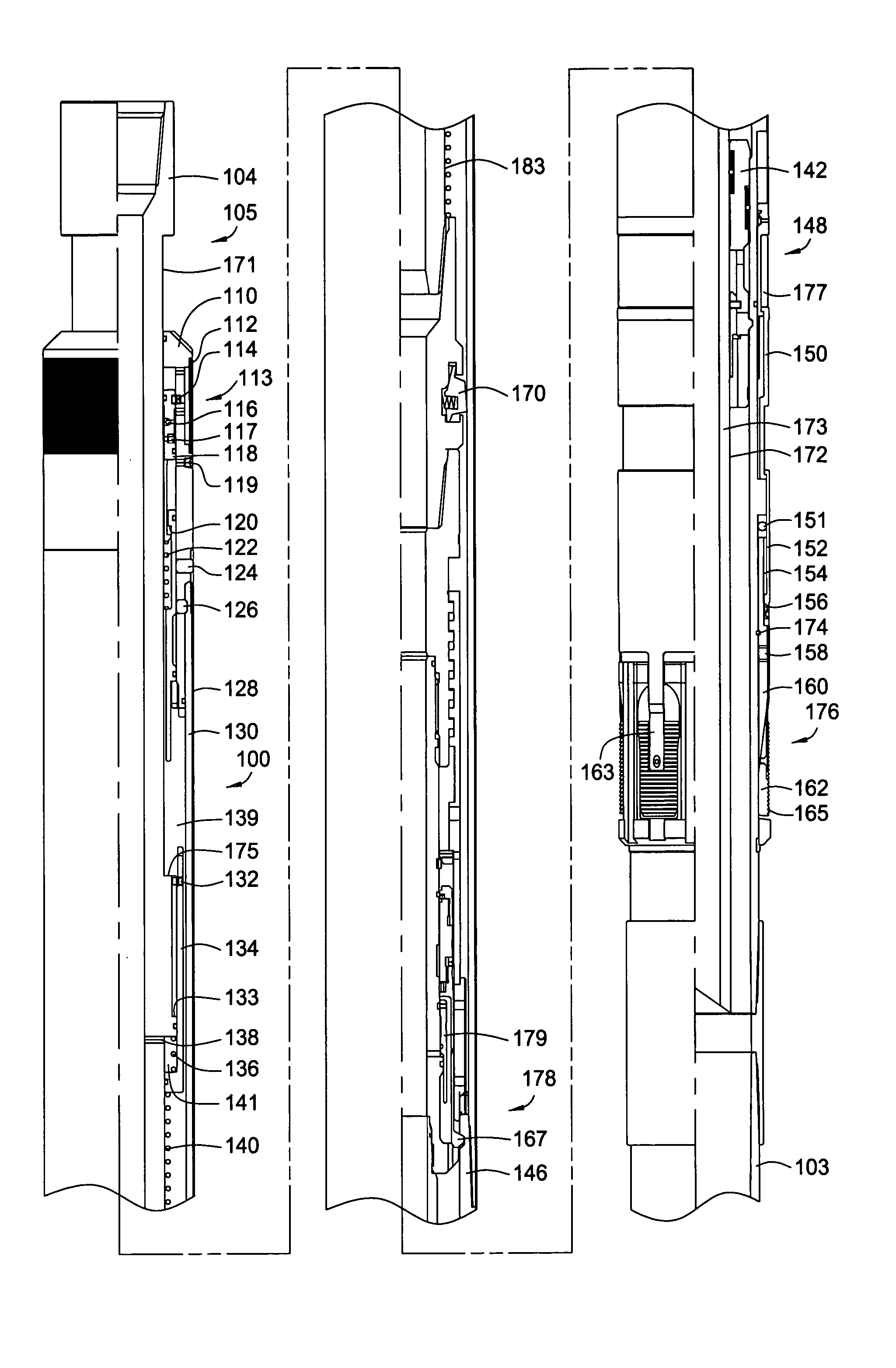
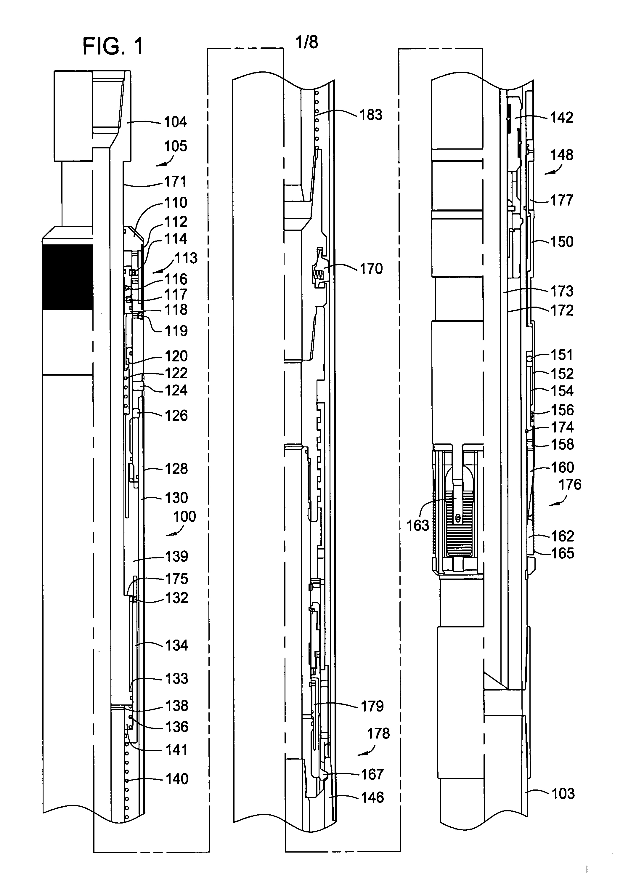
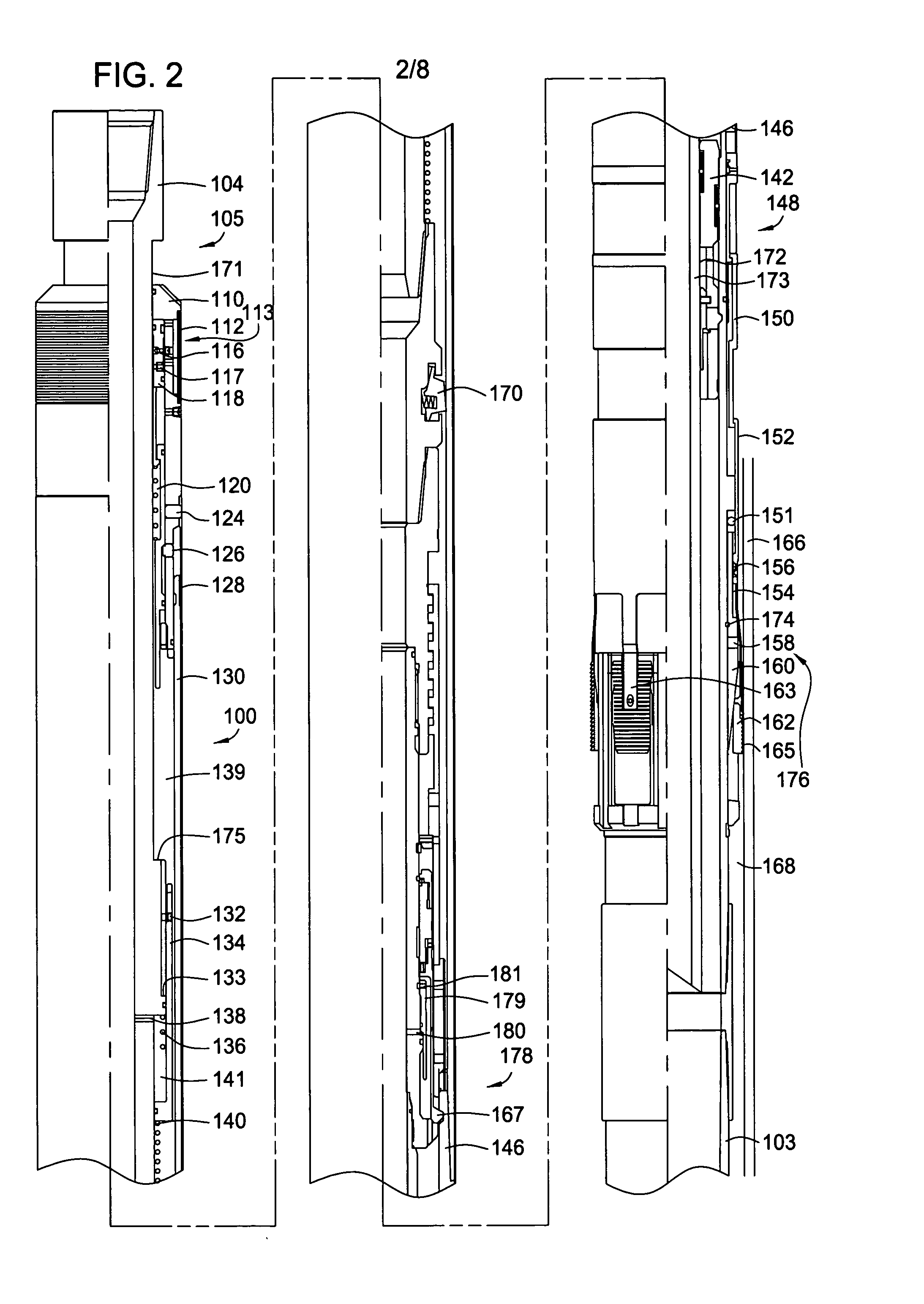
[0033]FIG. 1 illustrates a partial schematic view of one embodiment of a liner hanger assembly 100 and a running tool assembly 105 in a run-in position. FIG. 2 shows a partial schematic view of the liner hanger assembly 100 and the running tool assembly 105 with the liner hanger 176 set within a wellbore. FI...


PUM


Abstract

Embodiments of the present invention relates to hydraulically actuated tools, which may be used to actuate a liner hanger assembly. In one embodiment, the present invention provides a hydraulic setting tool for use in wellbore operations. The setting tool includes a first tubular member and a second tubular member disposed around the outer diameter of the first tubular member. A piston is mechanically attached to an upper portion of the second tubular member and adapted to move axially in relation to the first tubular member. The piston acts to transmit a force to the second tubular member. A slip assembly is operatively connected to the second tubular member and the second tubular member transmits the force to the slip assembly thereby actuating the slip assembly.

Description

CROSS-REFERENCE TO RELATED APPLICATIONS [0001] This application claims benefit of co-pending U.S. Provisional Patent Application Ser. No. 60 / 471,870, filed on May 20, 2003, which application is incorporated by reference herein in its entirety.BACKGROUND OF THE INVENTION [0002] 1. Field of the Invention [0003] Embodiments of the present invention generally relate to methods and apparatus for completing a well. Particularly, embodiments of the present invention relate to hydraulically actuated tools, which may be used to set a liner hanger assembly. [0004] 2. Description of the Related Art [0005] In the drilling of oil and gas wells, a wellbore is formed using a drill bit that is urged downwardly at a lower end of a drill string. After drilling to a predetermined depth, the drill string and the bit are removed and the wellbore is lined with a string of casing. An annular area is thus formed between the string of casing and the formation. A cementing operation is then conducted in orde...

Claims


Application Information

Patent Timeline
Patent Type & Authority Applications(United States)
IPC IPC(8): E21B23/04E21B43/10
CPCE21B43/10E21B23/04E21B23/06
Inventor HIRTH, DAVID E.MAGUIRE, PATRICK G.
Owner WEATHERFORD TECH HLDG LLC
Learn More