Method and device for bearing seal pressure relief

a technology of bearing seal and pressure relief, which is applied in the direction of bearing components, shafts and bearings, ball bearings, etc., can solve the problems of premature bearing failure, deformation of seal lip, etc., and achieve the effect of increasing the pressure and increasing the speed of pressur

Inactive Publication Date: 2005-01-13
NEW POWER CONCEPTS
View PDF99 Cites 19 Cited by
  • Summary
  • Abstract
  • Description
  • Claims
  • Application Information

AI Technical Summary

Benefits of technology

[0005] In an embodiment of the invention, a bearing includes a rolling element, a lubricant and a seal. The seal contains a hole that allows the internal bearing pressure to equalize with the external pressure of an engine pressure vessel containing the bearing, while the vessel is pressurized. In another embodiment of the invention, a gas-permeable membrane covers the hole. This embodiment allows for holes of greater size than the preceding embodiment. Larger size holes allow the interior and exterior pressures to equalize more quickly, allowing the engine vessel to be pressurized more rapidly.

Problems solved by technology

When the engine operates and turns the inner race, the deformed seal lip may be further destroyed.
This loss of lubricant from the bearing will cause premature bearing failure.

Method used


Image

  • Method and device for bearing seal pressure relief
  • Method and device for bearing seal pressure relief
  • Method and device for bearing seal pressure relief

Examples


Embodiment Construction

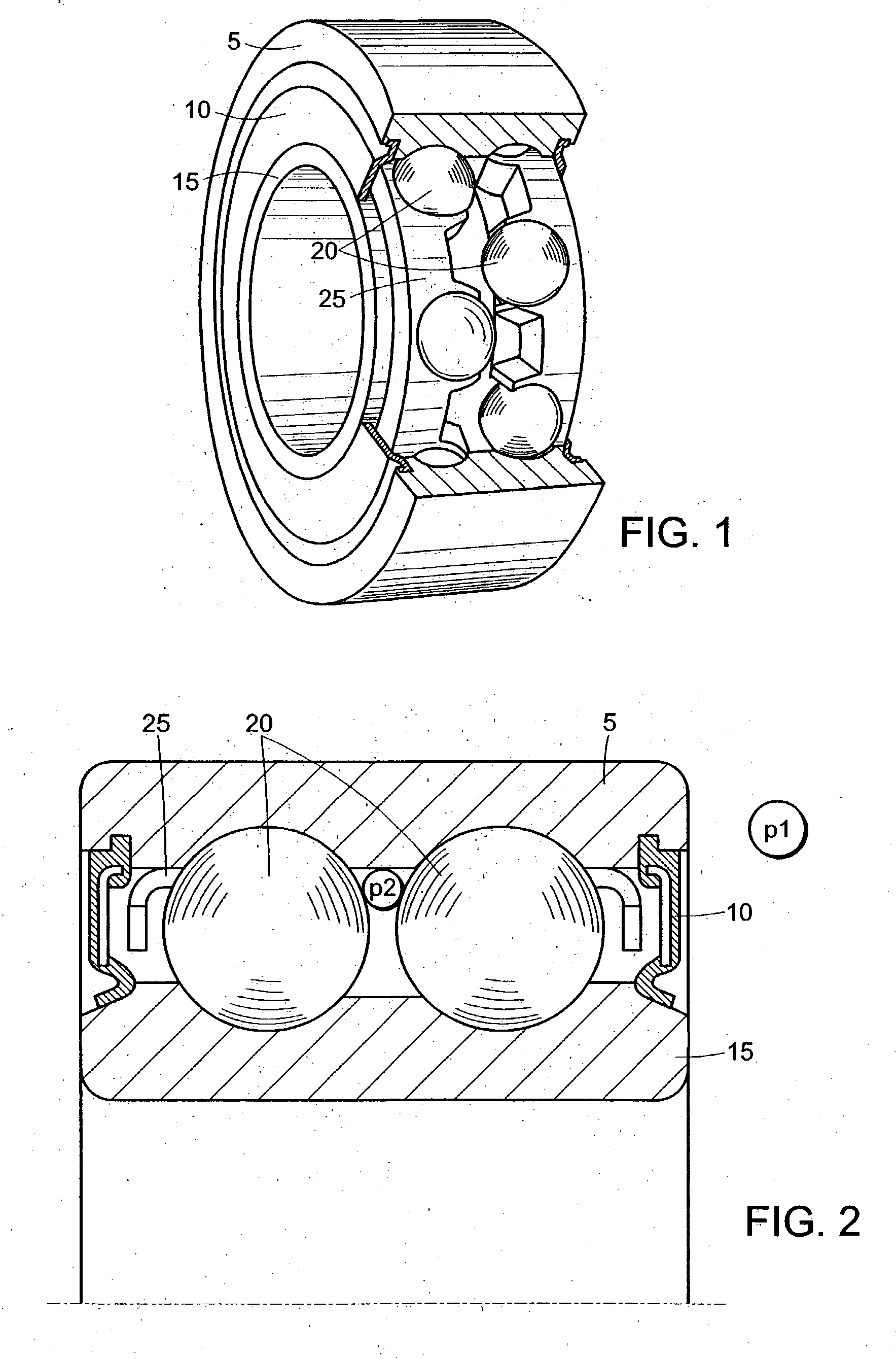
[0014] In embodiments of the present invention, seals for a rolling element bearing that allows gas leakage through the seal while effectively retaining lubricant are provided. These embodiments ensure that an engine vessel containing the bearing can be pressurized in a reasonable time without damaging the bearing seals.

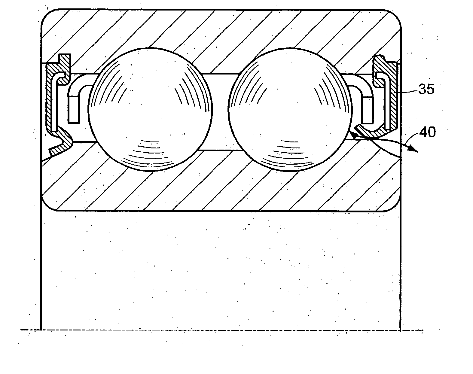
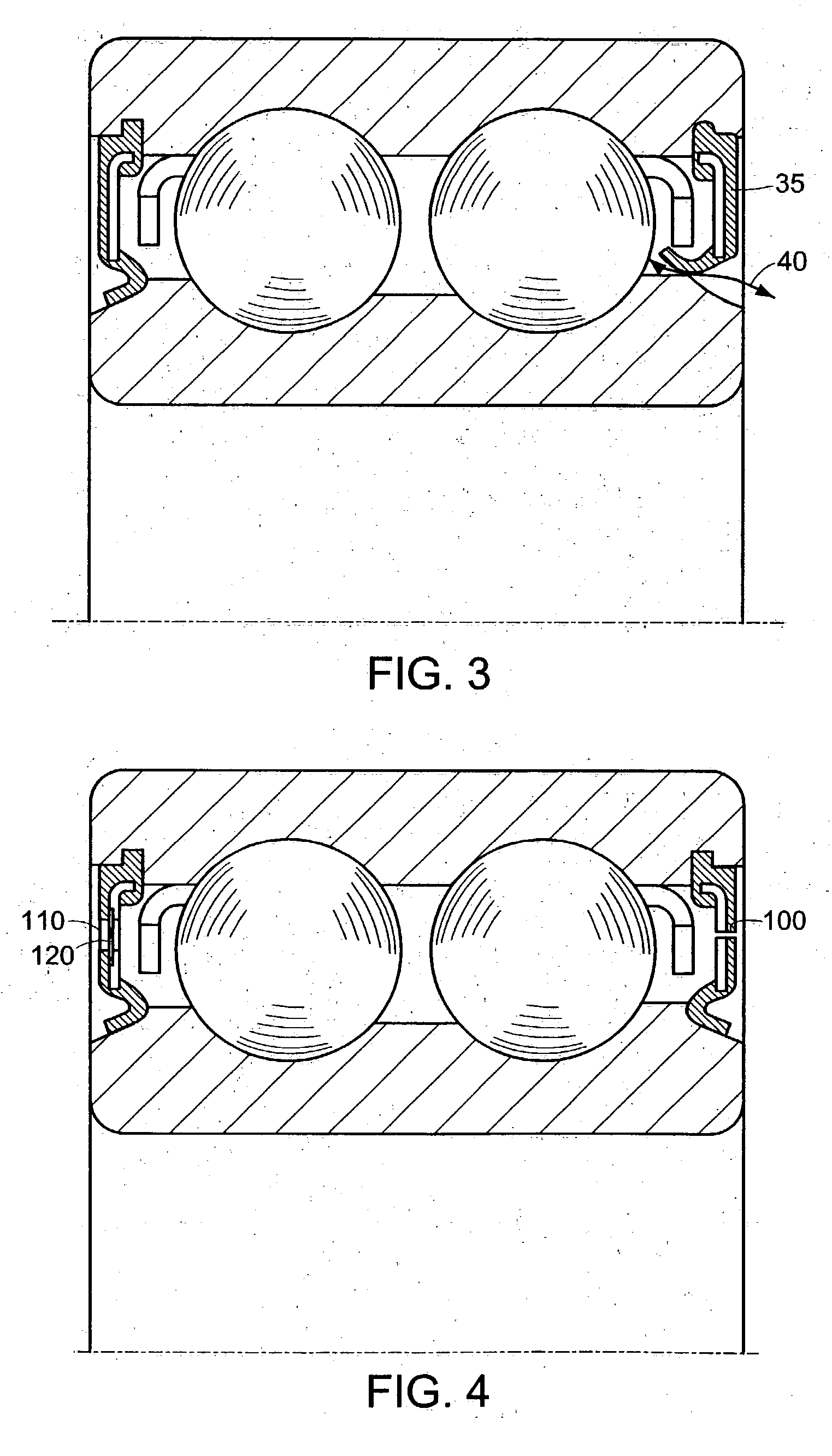
[0015] As shown in FIG. 4, in a first embodiment of the invention, a bearing seal is provided with a relief hole 100. The relief hole 100 is provided in one or both of the seals of a rolling element bearing. The hole may be preferably 0.004-0.014″ in diameter if circular, or of asimilar size if non-circular. This hole allows gas to enter the bearing inner space, equalizing the pressure inside and outside the bearing. The hole prevents the seal from imploding as the engine vessel is pressurized. The lubricant continues to be constrained to the space within the bearing, since the lubricant's viscosity is high enough that the lubricant will not leak out of a hole of th...


PUM


Abstract

An improvement to a sealed bearing allowing the pressure between the interior and exterior of a sealed bearing in a pressurized vessel, such as a Stirling engine, to equalize quickly. The device includes a small pressure relief hole in the bearing seal. The relief hole allows the pressure to equalize as the engine is pressurized, avoiding damage to the seal. The hole is sized so that the viscosity of the lubricant prevents leakage through the hole. Alternatively, the device may include lip seals that deform to allow the pressure to equalize.

Description

TECHNICAL FIELD [0001] The present invention pertains to methods and devices for preventing damage to bearing seals in a pressurized vessel. BACKGROUND OF THE INVENTION [0002]“Lube-for-life” rolling element bearings typically use a rubber lip seal to retain lubricants and to keep contaminants out. Retention of lubricant is very important for long, reliable operation of such bearings. [0003]FIGS. 1 and 2 present double row ball bearings with seals as a typical example of rolling element bearings. FIG. 1 is an isometric view with a quarter of the outer-race removed. The inner race 15 is typically pressed onto a shaft, while the outer race 5 is pressed into a drive component such as a connecting rod. The rolling elements 20 may include, without limitation, ball, needle, cylindrical and spherical elements. The cage 25 distributes the bearings around the circumference of the races. A lubricant (not shown) is generally required between the rolling elements and the races to ensure long bea...

Claims


Application Information

Patent Timeline
Patent Type & Authority Applications(United States)
IPC IPC(8): F16C33/78
CPCF16C33/7853F16C19/08F16C33/726
Inventor BHAT, PRASHANTLANGENFELD, CHRISTOPHER C.STRIMLING, JONATHAN
Owner NEW POWER CONCEPTS
Why Eureka
Try Eureka