Battery and a battery encapsulation

a battery and encapsulation technology, applied in the field of batteries, can solve the problems of loss of space that could otherwise have been used as battery space, heat being generated in the very vicinity, and heat negatively affecting the battery or the insulating material covering, and achieve the effect of better use of spa

Inactive Publication Date: 2005-01-27
ST JUDE MEDICAL
View PDF2 Cites 31 Cited by
  • Summary
  • Abstract
  • Description
  • Claims
  • Application Information

AI Technical Summary

Benefits of technology

[0012] It is an object of the present invention to provide a battery unit having a battery and a battery encapsulation of the type initially described that permits better use of space for the battery in the encapsulation than in known units, while at the same time permitting welding of the encapsulation parts with the battery in place without damaging the battery or any insulating material deposited thereon because of heat emanating from the weld.

Problems solved by technology

Welding will result in heat being generated in the very vicinity of the battery itself.
The heat might negatively affect the battery or the insulating material covering it since the battery is located dc se to the weld during the welding.
However, some space that could otherwise have been used as battery space is lost in the encapsulation due to the presence of the support element.
The support element also adds cost to the battery unit.

Method used


Image

  • Battery and a battery encapsulation
  • Battery and a battery encapsulation

Examples


first embodiment

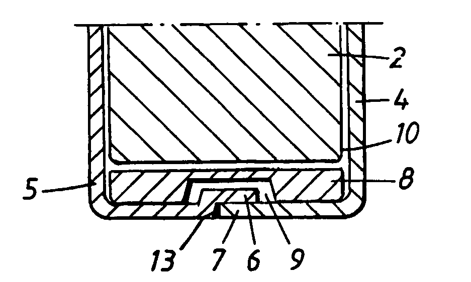
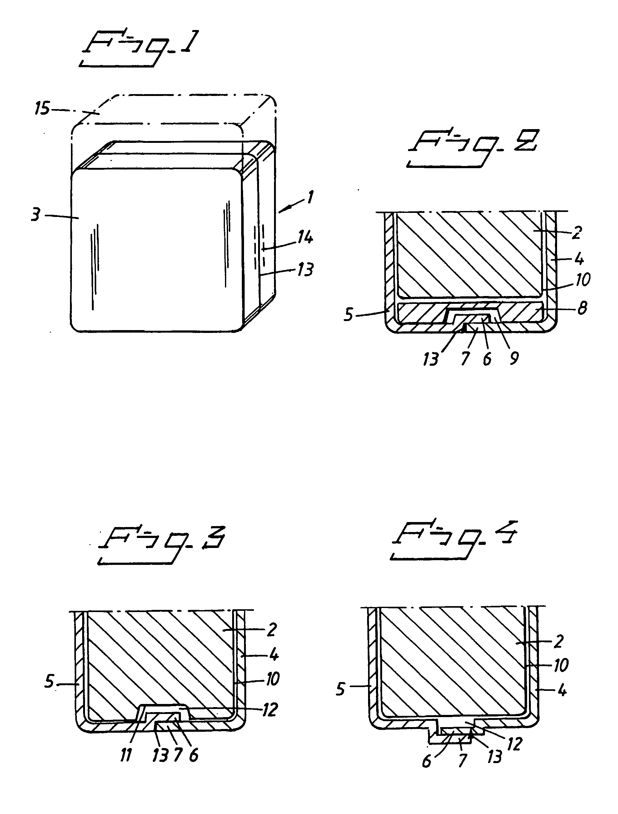
[0034]FIG. 3 shows the inventive battery unit1. Here, the battery 2 has a recess 11 extending along a region corresponding to the weld zone 14 adjacent the battery 2, such that a heat insulating space 12 is formed between the battery 2 and the encapsulation 3 along this part of the weld zone 14. Thereby excessive heat transfer is prevented from damaging the battery 2 or its insulation material 10. It is evident that only the part of the battery 2 that is facing the weld zone 14 need be provided with the recess 11. Normally, at least three out of the four of a generally flat, rectangular battery's small sides need to be provided with this recess. A recess is not necessary in the fourth small side of the battery that faces the electronics, if preferred from a production cost saving point of view.

[0035] The length of the recess 11 corresponds to the length of the part of the weld 13 that it faces. The depth of the recess 1 is such that an insulating space of 0.05 to 0.30 mm is obtained...

second embodiment

[0037]FIG. 4 shows the inventive battery unit 1. Here, the recess in the battery 2 has been replaced by a corresponding convexity of the edges 6,7 of the encapsulation. That is, the edges 6,7 are pre-bent before welding such that, with a conventional flat battery 2 inside the encapsulation 3, there will be an insulating space 12 between the battery 2 and inner periphery of the encapsulation along the weld zone 14.

[0038] The edges 6,7 are bent away from the interior of the encapsulation to such an extent that the heat insulating space thereby obtained has a width and a depth corresponding to the one mentioned above for the first embodiment.

[0039] It should be understood that the above embodiments have been disclosed only as an example, and that the invention is not restricted to these embodiments. A number of alternative embodiments will be apparent to those skilled in the art without departing from the inventive concept.

[0040] For example, in the first embodiment, the small sides ...


PUM

PropertyMeasurementUnit
depthaaaaaaaaaa
depthaaaaaaaaaa
widthaaaaaaaaaa

Abstract

A battery unit comprising a battery (2), and a battery encapsulation (3), comprising first and second encapsulation parts (4, 5) joined by a weld along a weld zone (14), the battery (2) being located in the encapsulation (3). The battery (2) comprises a recess (11) extending along the weld zone (14), such that a heat insulating space (12) is formed between the battery (2) and the encapsulation (3) along the weld zone (14).

Description

BACKGROUND OF THE INVENTION [0001] 1. Field of the Invention [0002] The present invention relates to a battery adapted to be located in a battery encapsulation, of the type having first and second encapsulation parts joined by a weld along a weld zone. [0003] The invention also relates to such a battery encapsulation, and a battery unit having such a battery and such a battery encapsulation, the battery being located in the encapsulation. [0004] The invention also relates to an implantable medical device that has such a battery unit. Typically, the implantable medical device is a heart stimulating apparatus. [0005] It should be noted that the invention particularly relates to a battery unit, a battery and a battery encapsulation wherein the first and second encapsulation parts are joined by welding with the battery being disposed in the encapsulation, generally in its operative position in the encapsulation. [0006] 2. Description of the Prior Art [0007] Since the invention is partic...

Claims


Application Information

Patent Timeline
Patent Type & Authority Applications(United States)
IPC IPC(8): A61N1/375H01M2/10
CPCH01M2/1055A61N1/375H01M50/213Y02E60/10
Inventor DAHLBERG, KENNETH
Owner ST JUDE MEDICAL
Why Eureka
Try Eureka