Golf club head

a golf club and club head technology, applied in the field of golf club heads, can solve the problems of affecting the center of gravity of the club head, affecting the size of the golf club head, and imparting more energy, and achieve the effect of high initial velocity and greater forgiveness

Inactive Publication Date: 2005-02-03
TAYLOR MADE GOLF
View PDF12 Cites 11 Cited by
  • Summary
  • Abstract
  • Description
  • Claims
  • Application Information

AI Technical Summary

Benefits of technology

[0015] The present invention provides a solution to enable club designers to overcome the problems described above, including a golf club head that exhibits greater forgiveness across a substantial portion of the striking face while continuing to impart high initial velocity to a golf ball.
[0027] The present invention provides a solution to enable club designers to overcome the problems described above, including a golf club head that exhibits greater forgiveness across a substantial portion of the striking surface while continuing to impart high initial velocity to a golf ball.

Problems solved by technology

There are limitations on how large a golf club head can be manufactured, which is a function of several parameters, including the material, the weight of the club head, the strength of the club head, and the materials used.
As a result, as the striking face becomes thinner, it has a tendency to deflect more and more at impact, and thereby has the potential to impart more energy to the ball.
These power bars and cones involve significant additional mass extending toward a rear of the club head, thus affecting the club head's center of gravity.
However, such club heads do not provide a coefficient of restitution (COR) that is at least the minimum value of approximately 0.8 that is sought by today's golfers.
In each of the foregoing examples, however, there is ultimately a failure to provide significant forgiveness to off-center hits.
For these clubs, the point of impact must still be at the sweet spot in order for these clubs to deliver their highest COR, and even the slightest deviation of the impact from the sweet spot will result in a significant loss in ball velocity.

Method used


Image

  • Golf club head
  • Golf club head
  • Golf club head

Examples


Embodiment Construction

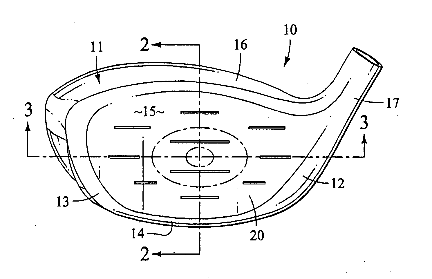
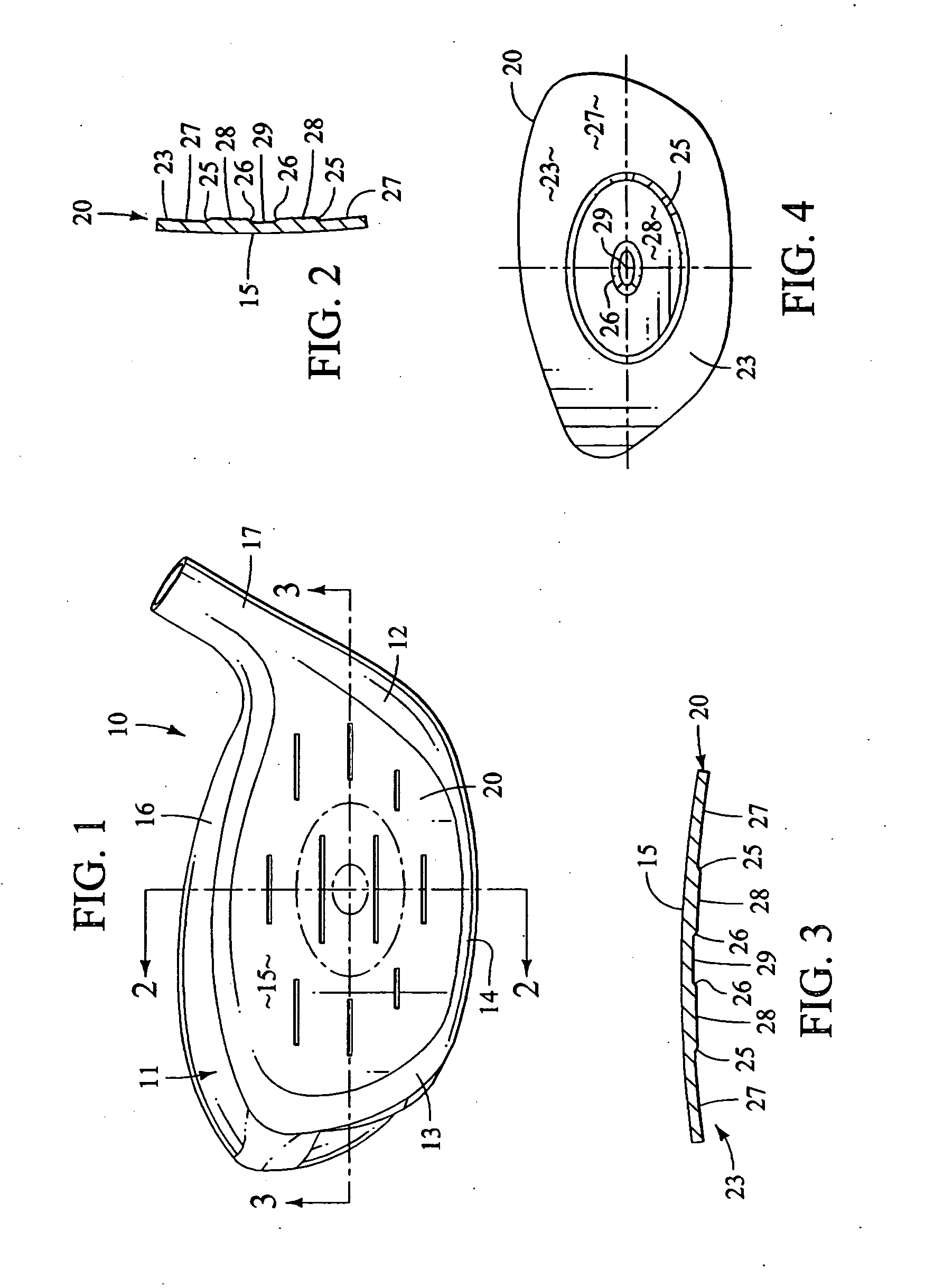
[0050] The drawings depict several preferred embodiments of a golf club head in accordance with the present invention. With reference to FIG. 1, a club head 10 is shown that is similar to many metal wood club heads that are known in the art. Club heads within the scope of the invention are not necessarily limited to the shape depicted. The club head comprises a hollow metallic body 11 and a striking or face plate 20. The body comprises a heel portion 12, a toe portion 13, a sole portion 14 and a crown portion 16 that cooperate to define an opening (not shown) that receives the striking plate. The striking plate is shown in greater detail in FIGS. 2-4. The club head is normally connected to a shaft (not shown) by a hosel 17 that is integrally formed with the body. Preferably, the body is constructed of stainless steel or a titanium alloy, but alternatively can be constructed of other materials such as a silicon steel alloy, various composites, and combinations thereof. The club head ...


PUM


Abstract

A golf club head is provided having a substantially increased sweet spot across its striking face. A preferred embodiment includes a striking plate with a substantially annular area on a rear surface that has an increased thickness or stiffness surrounding the central region of the balance point of the striking surface. The central region of the striking plate has a generally reduced thickness or stiffness that is less than the maximum thickness or stiffness values found at the third and fourth thickness or stiffness profiles of the substantially annular area but greater than a minimum thickness or stiffness values at the peripheral area. The first and second thickness or stiffness profiles of the substantially annular area have thicknesses or stiffnesses less than the maximum values of the third and fourth thickness or stiffness profiles but more than the minimum thickness or stiffness values at the periphery.

Description

CROSS-REFERENCE TO RELATED APPLICATIONS [0001] This is a continuation of application Ser. No. 10 / 302,331, filed Nov. 22, 2002, which is a continuation-in-part of application Ser. No. 09 / 898,843, filed Jul. 3, 2001, both of which are herein incorporated by reference.BACKGROUND OF THE INVENTION [0002] The present invention relates generally to golf club heads and, more particularly, to golf club heads having an improved face construction. [0003] Modem golf clubs have typically been classified as woods, irons or putters. Additionally, a newer class of golf clubs termed “utility” clubs or “iron woods” seek to replace low lofted long irons or higher numbered fairway woods. The term “wood” is a historical term that is still commonly used, even for golf clubs that are constructed of steel, titanium, fiberglass and other more exotic materials, to name a few. The woods are now often referred to as “metal woods.” The term “iron” is also an historical term that is still commonly used, even tho...

Claims


Application Information

Patent Timeline
Patent Type & Authority Applications(United States)
IPC IPC(8): A63B53/04
CPCA63B53/04A63B2053/0412A63B2053/0408A63B2053/0458A63B53/0466A63B2053/0416A63B53/0412A63B53/0458A63B53/0408A63B53/0416A63B60/00
Inventor WILLETT, KRAIG A.HOFFMAN, JOSEPH H.BURNETT, MICHAEL SCOTT
Owner TAYLOR MADE GOLF
Why Eureka
Try Eureka