Cervical plate with backout protection

a cervical plate and backout technology, applied in the field of implantable devices, can solve the problems of difficult insertion of bone grafts into the vacated space and fuse the adjacent vertebra

Inactive Publication Date: 2005-02-03
ZIMMER BIOMET SPINE INC
View PDF30 Cites 236 Cited by
  • Summary
  • Abstract
  • Description
  • Claims
  • Application Information

AI Technical Summary

Problems solved by technology

Currently, it is difficult to insert the bone graft into the vacated space and fuse the adjacent vertebrae.

Method used


Image

  • Cervical plate with backout protection
  • Cervical plate with backout protection
  • Cervical plate with backout protection

Examples


Embodiment Construction

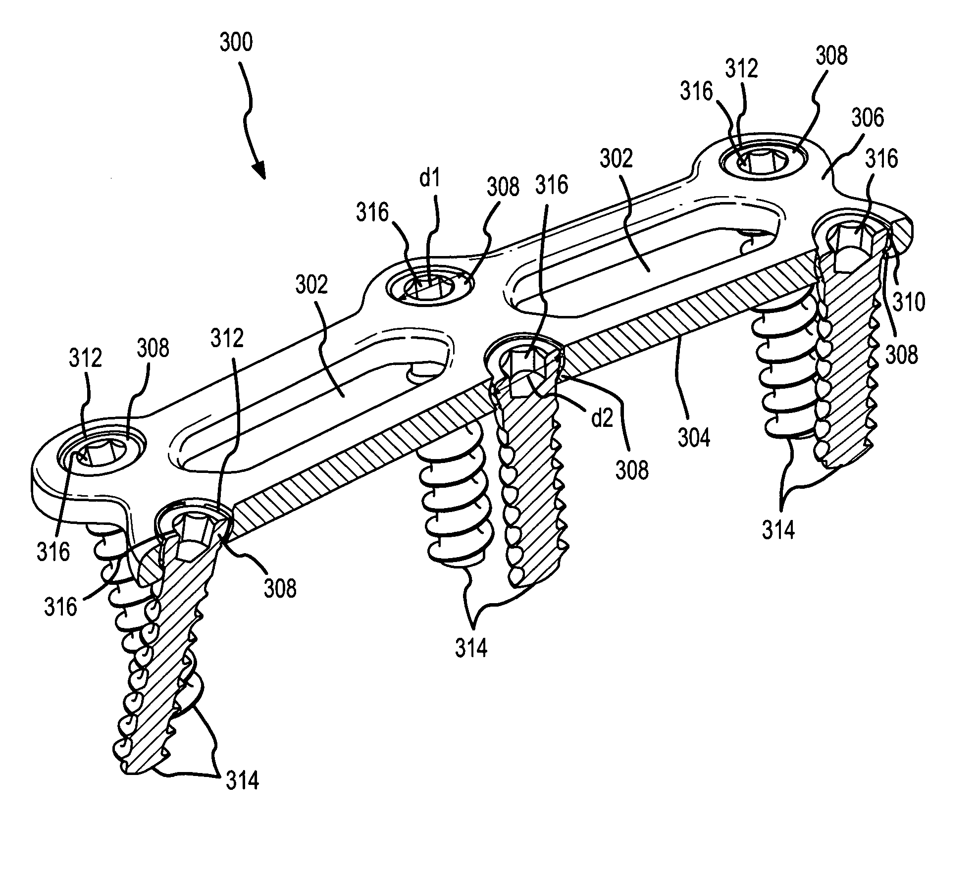
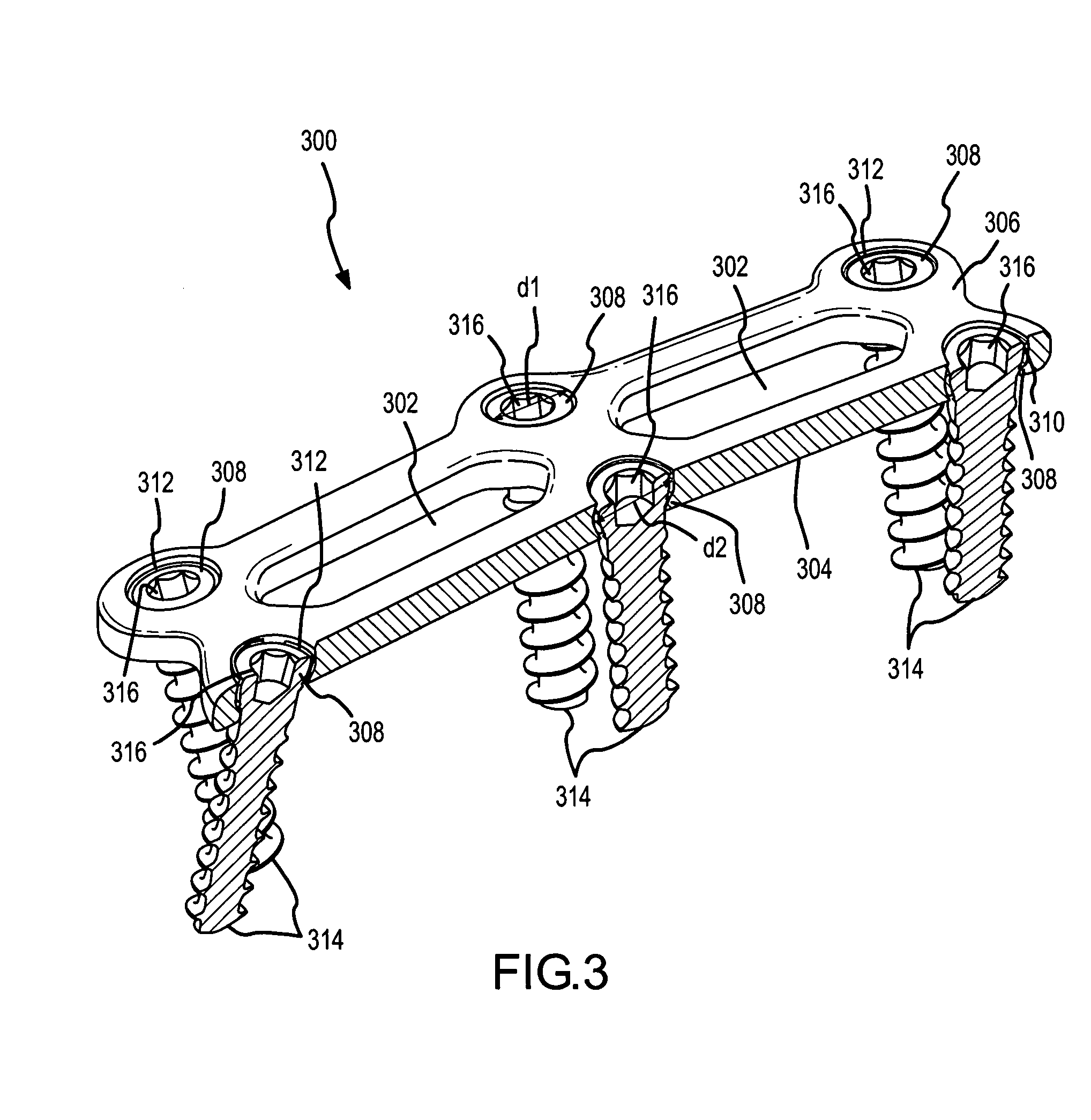
[0020] The present invention will be described with reference to FIGS. 3-8. Referring first to FIG. 3, a perspective and cross-sectional view of a cervical plate 300 illustrative of an embodiment of the present invention is shown. Cervical plate 300 is shown with a construct that could span two intervertebral spaces (a.k.a. a two level cervical plate); however, cervical plate 300 could be constructed to span more or less intervertebral spaces. Because plate 300 spans two intervertebral spaces, cervical plate 300 is shown with two viewing windows 302. More or less viewing windows 302 could be provided. For example, for a construct that spanned one intervertebral space, only one viewing window may be used. Moreover, for a construct that spanned three intervertebral spaces, three viewing windows may be provided. Furthermore, for cervical plate 300, each viewing window 302 could be split into several smaller viewing windows as a matter of design choice.

[0021] Cervical plate 300 compris...


PUM


Abstract

The present invention provides a cervical plate with backout protection. In particular, a bushing residing in each of a plurality of through holes has a bottom edge that aligns with a protrusion on a screw head. The bottom edge aligning with the protrusion inhibits reverse threading or backing out of the bone screw.

Description

RELATED APPLICATIONS [0001] This application is a continuation-in-part of U.S. patent application Ser. No. 10 / 632,760, filed Aug. 1, 2003, titled CERVICAL PLATE, which is a continuation in part of U.S. patent application Ser. No. 10 / 178,371, filed Jun. 24, 2002, titled CERVICAL PLATE, now U.S. Pat. No. 6,602,257.FIELD OF THE INVENTION [0002] The present invention relates to implantable devices useful in bone fusion and, more particularly, to cervical plates having backout protection. BACKGROUND OF THE INVENTION [0003] The vertebrae of the human spine are arranged in a column with one vertebra on top of the next. Between each vertebra exists an intervertebral disc that transmits force between adjacent vertebrae and provides a cushion between the adjacent vertebrae. [0004] Sometimes, back pain is caused by degeneration or other deformity of the intervertebral disk (“diseased disk”). Conventionally, surgeons treat diseased discs by surgically removing the diseased disc and inserting an...

Claims


Application Information

Patent Timeline
Patent Type & Authority Applications(United States)
IPC IPC(8): A61B17/02A61B17/70A61B17/80A61B17/92A61F2/28A61F2/44A61F2/46
CPCA61B17/7059A61B17/8047A61B17/809A61F2002/2835A61B2017/0256A61F2/4455A61F2/4601A61B17/92
Inventor THRAMANN, JEFFREYFULTON, MICHAELRAYMOND, SPANKY A.
Owner ZIMMER BIOMET SPINE INC
Why Eureka
Try Eureka