Resonant circuit and a voltage-controlled oscillator

a voltage-controlled oscillator and resonance circuit technology, applied in oscillator generators, angle modulation by variable impedence, electrical apparatus, etc., can solve the problems of unattainable ideal, heavy load on the voltage drop means used for generating such staircase control voltages, and steep inclination of the capacitance variation curve within the range of control voltages, etc., to achieve easy composition within an ic chip, improve the phase noise of the voltage-controlled oscillator, and increase the effect of power consumption

Inactive Publication Date: 2005-02-10
SONY ERICSSON MOBILE COMM JAPAN INC
View PDF6 Cites 54 Cited by
  • Summary
  • Abstract
  • Description
  • Claims
  • Application Information

AI Technical Summary

Benefits of technology

[0020] (1) The phase noise of the voltage-controlled oscillator can be improved.
[0021] (2) The voltage control sensitivity (Kv) of the voltage-controlled oscillator dependent on the physical characteristic of the MOS variable capacitance element is rendered adjustable by selection of the bias voltage.
[0022] (3) The variable capacitance element used in the present invention may consist of a MOS transistor, so that it can be composed easily within an IC chip to consequently realize improvements without any extreme increase of the power consumption.
[0023] (4) For attaining multi-step adjustment of the DC bias to the divided MOS variable capacitance elements, staircase

Problems solved by technology

And the inclination of the capacitance variation curve within the range of the control voltage is also steep.
Accordingly, there exists a problem that the voltage drop means used for generating such staircase control voltages becomes a heavy load on the charge pump circui

Method used


Image

  • Resonant circuit and a voltage-controlled oscillator
  • Resonant circuit and a voltage-controlled oscillator
  • Resonant circuit and a voltage-controlled oscillator

Examples


Embodiment Construction

[0042] Hereinafter some preferred embodiment of the present invention will be described in detail with reference to the accompanying drawings.

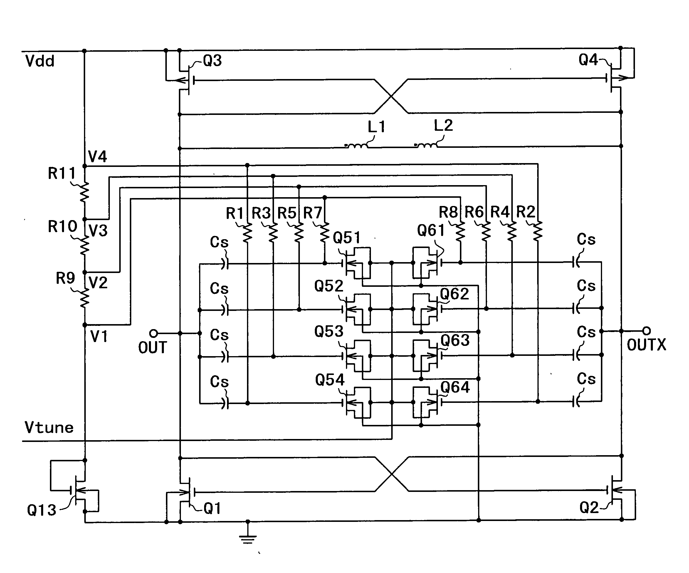
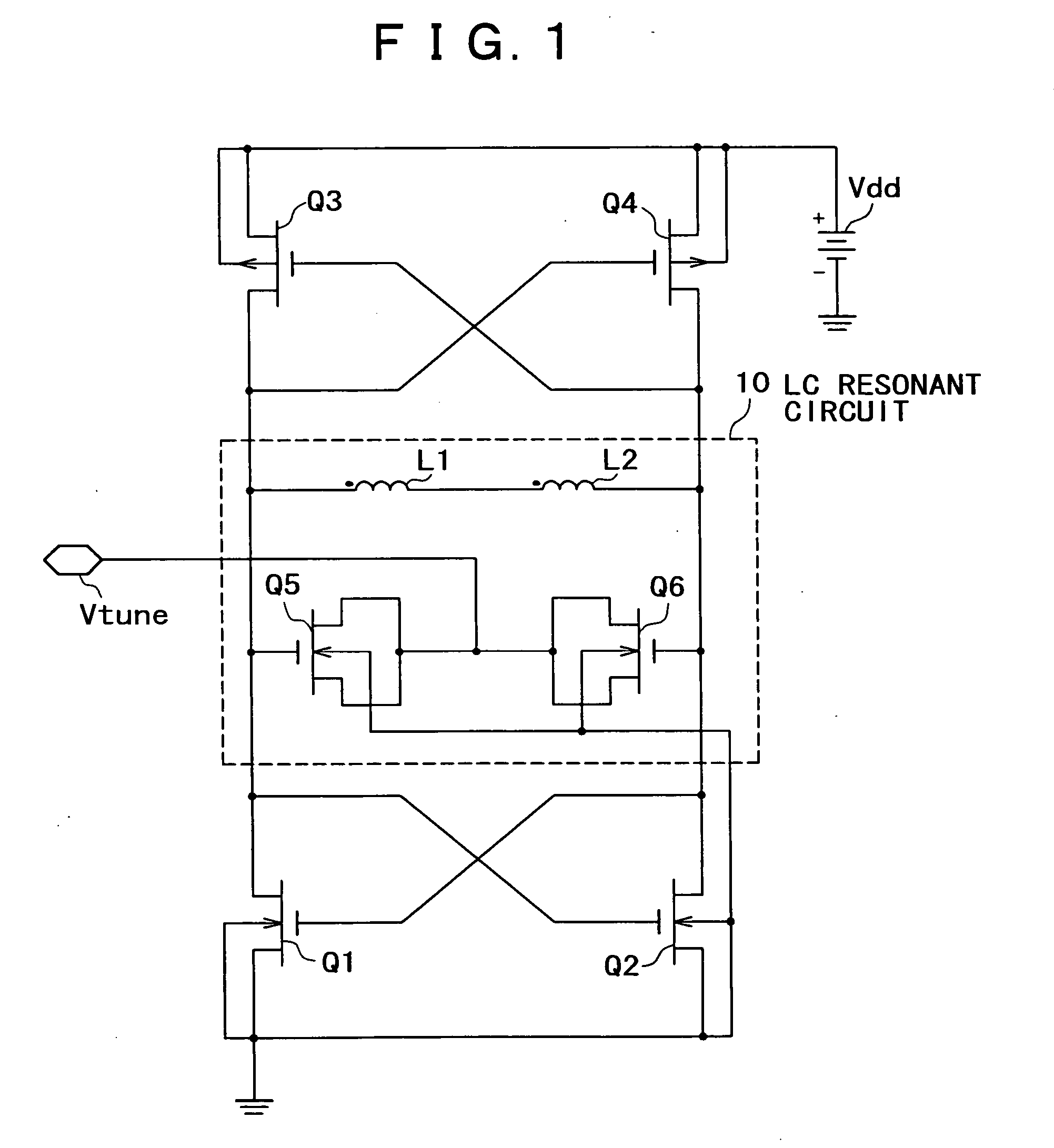
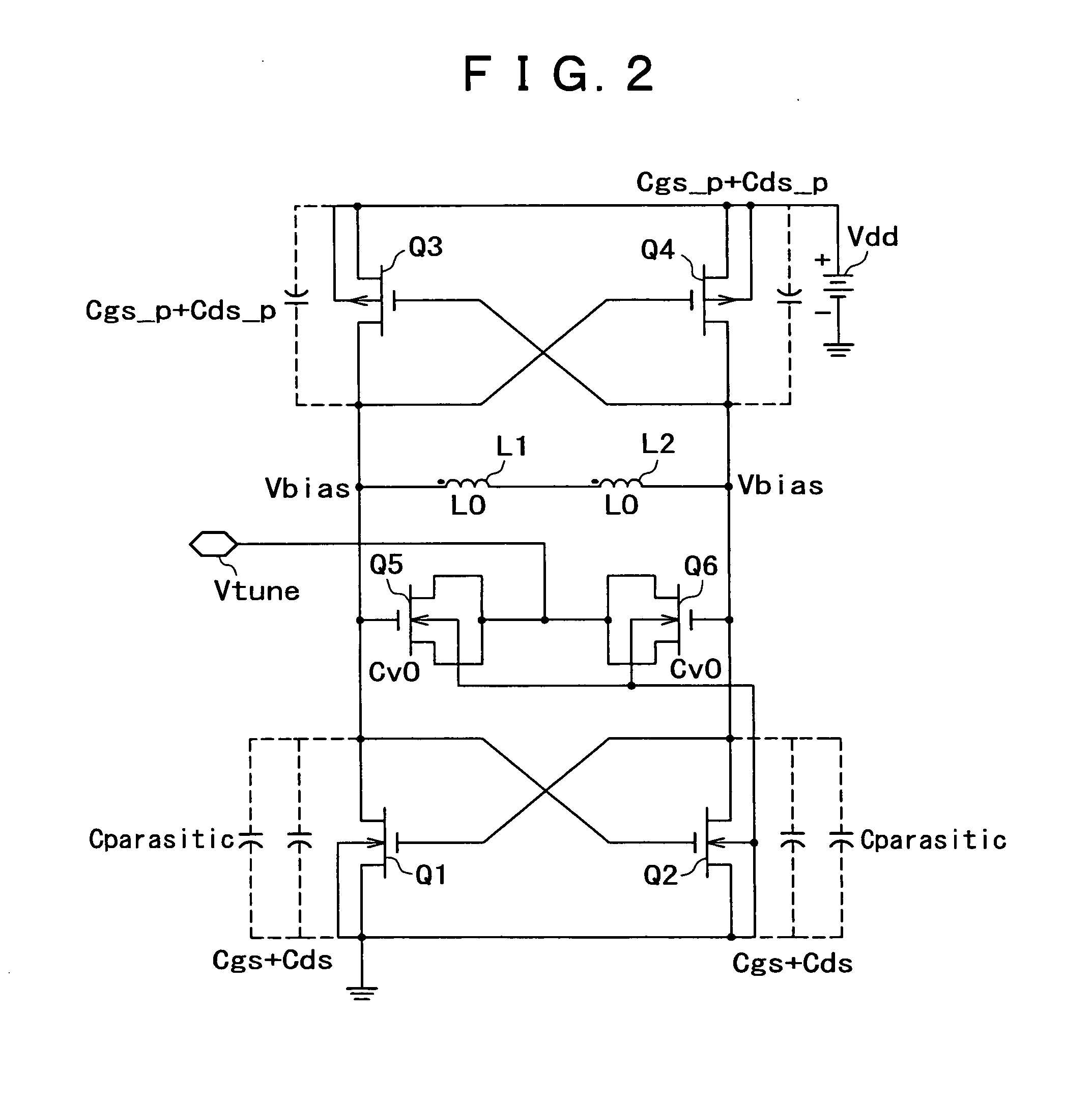
[0043] As shown in FIG. 5, the capacitance value of a MOS variable capacitance element consisting of MOS transistors Q5 and Q6 (FIG. 1) is varied very gently until immediately before the potential difference between the gate and the drain-source reaches the threshold voltage (Vth) of each transistor, and then is reduced steeply in the vicinity of the threshold voltage Vth.

[0044]FIGS. 6A and 6B show structural examples of a MOS transistor. Generally, one MOS transistor (FIG. 6A) having such variable capacitance characteristic as shown in FIG. 5 is divided into a group of nMOS transistors smaller in size (FIG. 6B), and the entire divided transistors are connected in parallel mutually to constitute substantially equal variable capacitance circuits. FIGS. 7A and 7B show, respectively, the structure of FIG. 6A and that of FIG. 6B with circuit con...


PUM


Abstract

A voltage-controlled oscillator comprising a resonant circuit and MOS transistors which constitute a negative resistance circuit of a differential structure. The resonant circuit consists of an inductance element and a MOS variable capacitance element connected in parallel therewith. The MOS variable capacitance element is divided into plural pairs connected in parallel with each other. A voltage division circuit generates staircase different-step DC bias voltages to be applied respectively to the gates of the plural divided MOS transistors. The divided MOS variable capacitance elements have a common terminal to which a common control voltage is applied. The resonant circuit is capable of reducing a load on the control voltage generator and improving the characteristics of the voltage-controlled oscillator.

Description

BACKGROUND OF THE INVENTION [0001] The present invention relates to a resonant circuit comprising an induction element and a MOS (Metal Oxide Semiconductor) variable capacitance element connected in parallel with the induction element, and also relates to a voltage-controlled oscillator using such a resonant circuit. [0002]FIG. 1 shows a circuit configuration of an LC resonance type voltage-controlled oscillator used in general. In this configuration, an LC resonant circuit 10 comprising nMOS transistors Q5, Q6 and inductance elements L1, L2 is connected to a first negative resistance circuit consisting of nMOS transistors Q1 and Q2, and also to a second negative resistance circuit consisting of PMOS transistors Q3 and Q4, wherein the voltage-controlled oscillator can be driven to oscillate at the resonance frequency of the resonant circuit. The MOS transistors Q5 and Q6 constitute a variable capacitance element whose capacitance value is varied by controlling a DC voltage applied t...

Claims


Application Information

Patent Timeline
IPC IPC(8): H03B5/12
CPCH03B2200/0062H03B5/1228H03B5/1253H03B5/1212H03B5/1296H03B5/1231
Inventor TAKAGI, KOTARO
Owner SONY ERICSSON MOBILE COMM JAPAN INC
Why Eureka
Try Eureka