Phase selection programmable frequency divider

A phase selection and frequency divider technology, applied in the field of frequency synthesizers, can solve the problems of limited frequency accuracy, logic errors, glitches, etc., to improve the overall phase noise, reduce in-band phase noise, and reduce the probability of errors.

Inactive Publication Date: 2009-03-04
RDA MICROELECTRONICS SHANGHAICO LTD
View PDF0 Cites 15 Cited by
  • Summary
  • Abstract
  • Description
  • Claims
  • Application Information

AI Technical Summary

Problems solved by technology

[0003] Existing programmable frequency dividers are mainly integer frequency dividers (integer-N) whose minimum frequency division can only be integers and fractional frequency dividers (fractional-N) that use retiming (retiming) to control phase selection, but this Both programmable frequency dividers have certain disadvantages
Among them, there are two potential problems in the phase-locked loop structure using an integer frequency division number: first, when there is no integer multiple relationship between the selectable reference clock frequency and the phase-locked loop output signal frequency, this phase-locked loop cannot be used, That is, the frequency accuracy is very limited; second, in many applications, a phase-locked loop using an integer frequency divider often needs to select a very low reference clock frequency, so that the loop bandwidth of this type of programmable phase-locked loop cannot be selected Large, which will increase the lock time of the phase-locked loop
However, the fractional frequency divider adopting retiming (retiming) to control phase selection will produce phenomena such as glitches in actual operation, and overly complex control logic will easily lead to instability of the entire frequency divider or lead to logic failure. go wrong

Method used


Image

  • Phase selection programmable frequency divider
  • Phase selection programmable frequency divider
  • Phase selection programmable frequency divider

Examples


Embodiment Construction

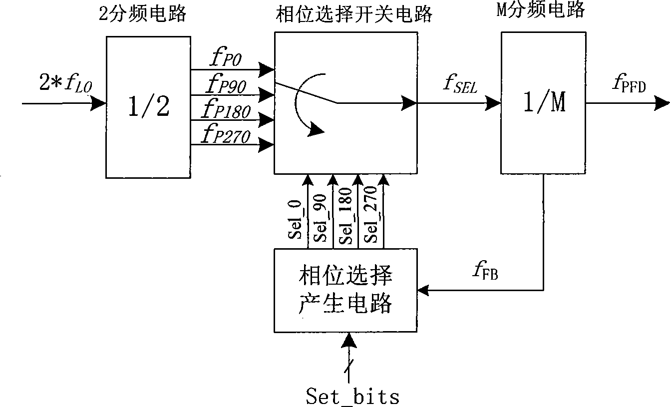
[0015] In one embodiment, such as figure 1 As shown, the phase selection programmable frequency divider of the present invention includes a 2 frequency division circuit, a phase selection switch circuit, a phase selection generation circuit and an M frequency division circuit.

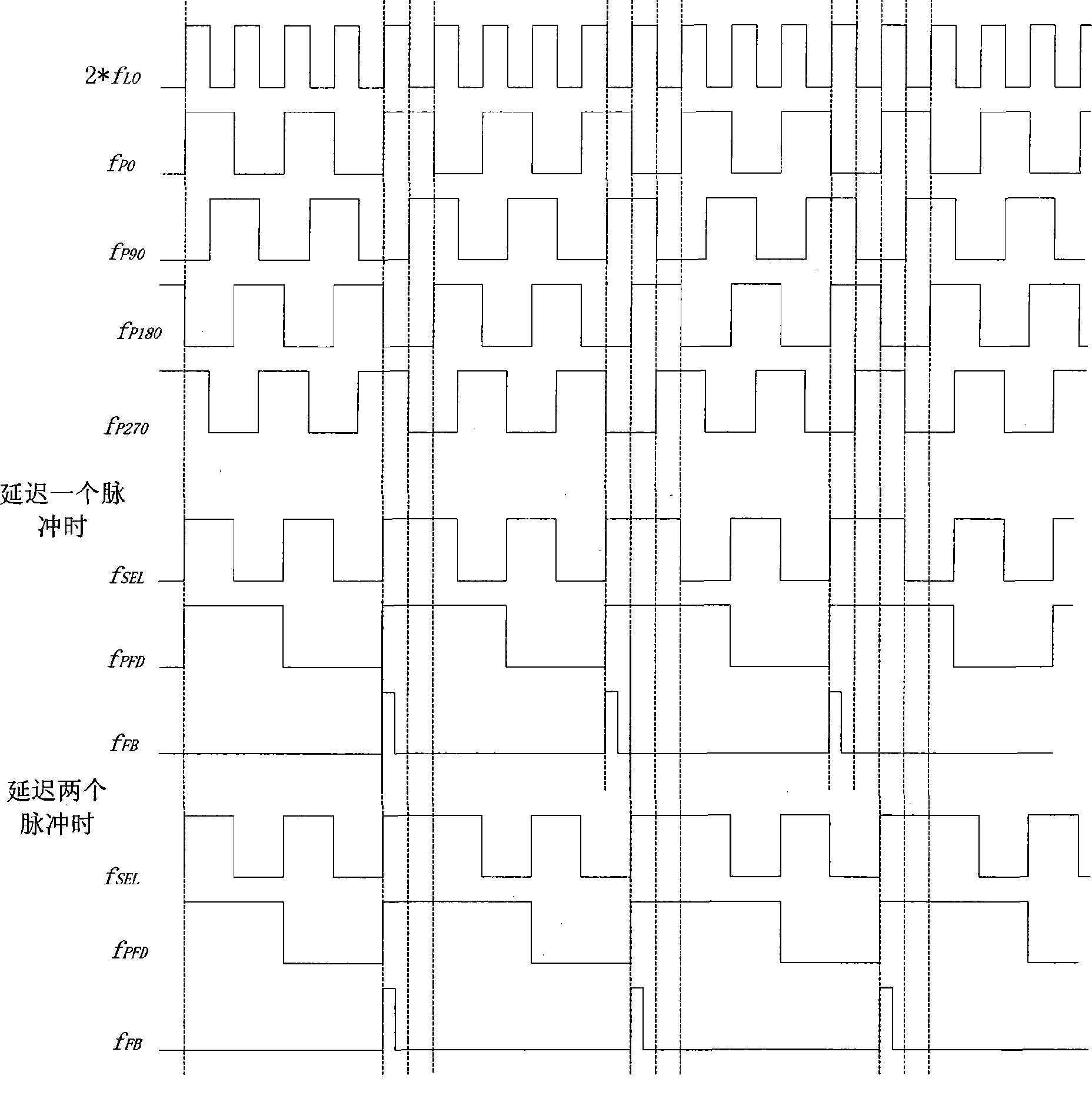
[0016] The 2 frequency division circuit is a 2 frequency division circuit with orthogonal output characteristics. In the present invention, the frequency of the input signal of the 2 frequency division circuit is 2 times the actual operating frequency of the system, i.e. 2*f L0 , its output signal is four signals f with a phase difference of 90 degrees P0 , f P90 , f P180 and f P270 , those skilled in the art should know that the frequencies of these four output signals are the same as the actual working frequency of the system.

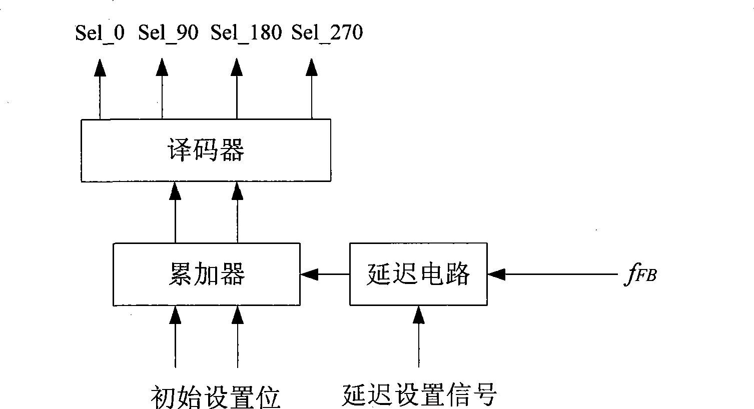
[0017] The phase selection switch circuit is used to select and output one of the four signals with a phase difference of 90 degrees under the control of the switching co...


PUM


Abstract

The invention discloses a phase selection programmable frequency divider, only an accumulator is needed in a phase selection generating circuit, thus simplifying the producing process of phase selection logic, improving the stability of the whole frequency divider, avoiding the generation of burrs in the phase selection process, and reducing the error possibility of the whole frequency divider; meanwhile, by pre-obtaining four signals working at the actual system working frequency and with the phase difference of 90 degrees, and causing the phase selection generating circuit to output a switching control signal used for controlling the phase selection switching circuit to be switched from the signal of one phase into the signal of another phase under the control of a trigger signal output by the M frequency divider, the frequency dividing value with the minimum value of 0.25 is realized, thus causing reference clock frequency to be improved to be four times of the prior one, namely, the sampling frequency of a Sigma-Delta modulator is improved to be four times of the prior one, thereby effectively reducing the in-band phase noise of a phase-locking loop and improving the entire phase noise of a frequency synthesizer.

Description

technical field [0001] The invention relates to a frequency synthesizer based on a phase-locked loop, in particular to a phase selection programmable frequency divider in the frequency synthesizer based on a phase-locked loop. Background technique [0002] As we all know, the programmable frequency divider is one of the components of the frequency synthesizer based on the phase-locked loop structure. The frequency synthesizer is widely used in receivers to generate local oscillator signals or in transmitters to generate carrier frequency signals. vibration signal. [0003] Existing programmable frequency dividers are mainly integer frequency dividers (integer-N) whose minimum frequency division can only be integers and fractional frequency dividers (fractional-N) that use retiming (retiming) to control phase selection, but this Both programmable frequency dividers have certain disadvantages. Among them, there are two potential problems in the phase-locked loop structure us...

Claims


Application Information

Patent Timeline
Patent Type & Authority Applications(China)
IPC IPC(8): H03K23/00H03L7/18
Inventor 魏述然杨胜君
Owner RDA MICROELECTRONICS SHANGHAICO LTD
Why Eureka
Try Eureka