Stabilizer for rotary tools

Active Publication Date: 2005-02-17
CUSTOM SPEC ENG
View PDF11 Cites 61 Cited by
  • Summary
  • Abstract
  • Description
  • Claims
  • Application Information

AI Technical Summary

Benefits of technology

[0005] The present invention makes adjustment possible of both the angle of the handle and its annular position

Problems solved by technology

Also, the work to be performed may be located in an awkward location and require the special positioning of the tool and its stabilizing means.
None of such devices permit

Method used


Image

  • Stabilizer for rotary tools
  • Stabilizer for rotary tools
  • Stabilizer for rotary tools

Examples


Embodiment Construction

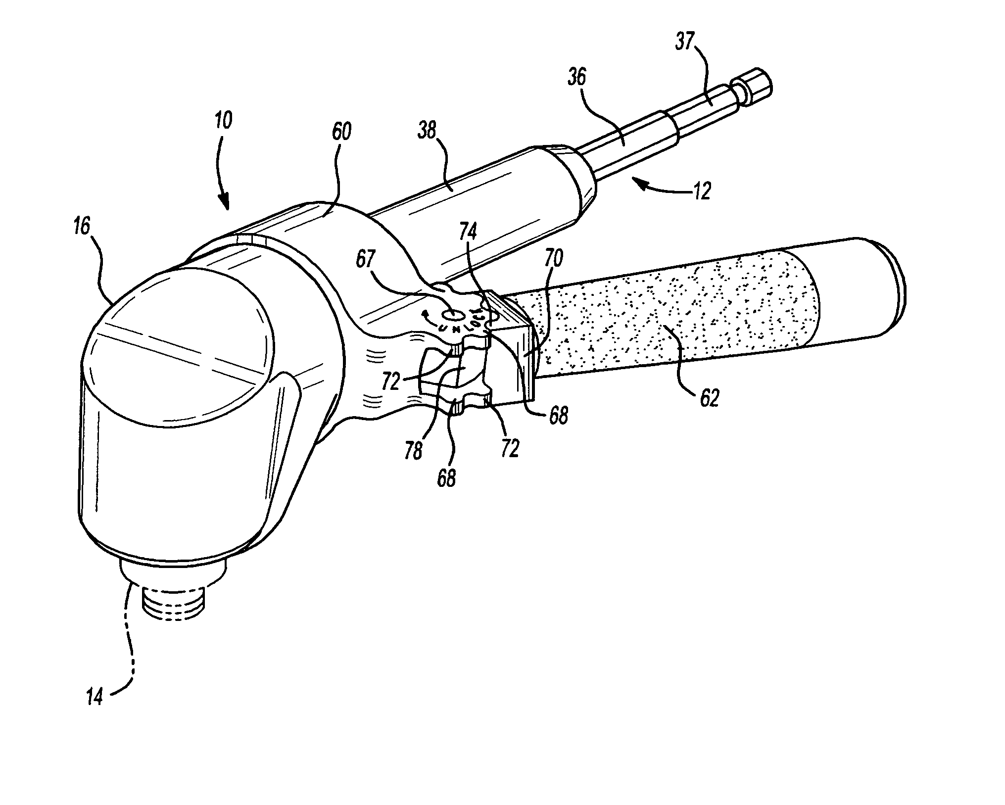
[0015] The drive head of the invention is designated generally at 10 and is adapted for attachment to powered rotary tools such as drills or screwdrivers a portion of one being indicated at 11 in FIG. 6 in which one hand of an operator can align and steady the drive head 10 and the other hand holds and triggers the drill 11. The head 10 is connected to such drills or drivers by way an input shaft 12 and is suitable for driving quick release drills or fastener drivers by way of a quick release output chuck 14.

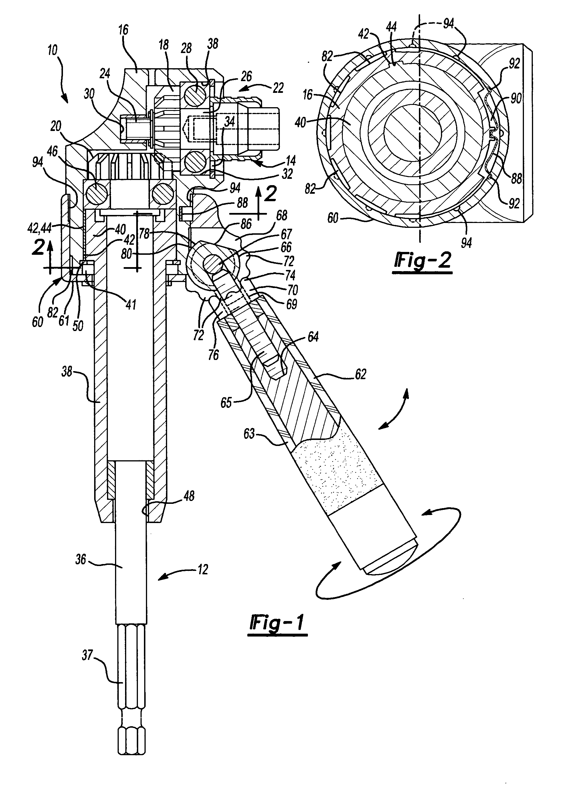
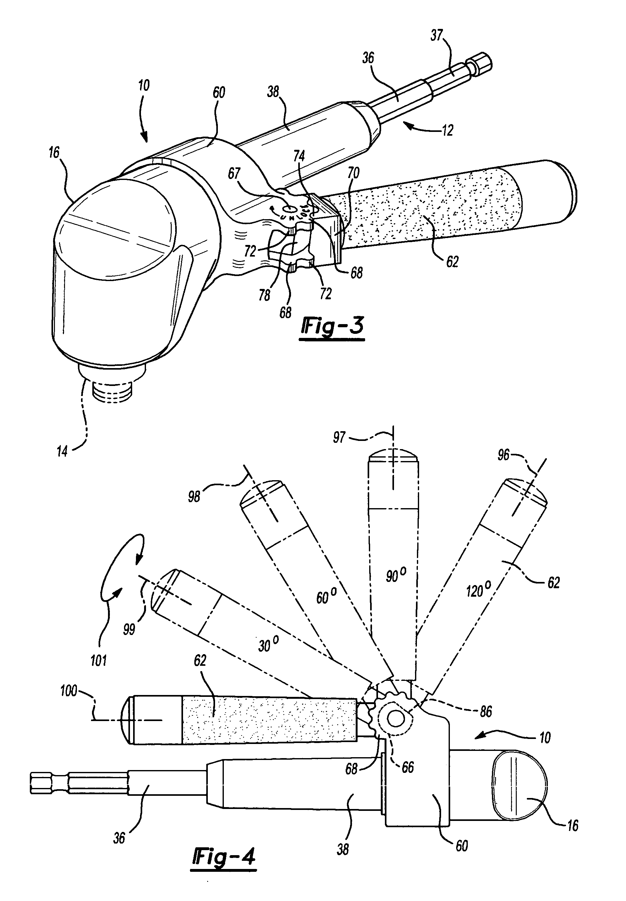
[0016] The drive head 10 includes a housing 16 which serves to support miter gears 18 and 20 as seen in FIG. 1 which change direction of drive from the tool motor a full ninety degrees (90°) from the input shaft 12 to the axis of output chuck 14.

[0017] Miter gear 18 forms part of an output assembly 22 which includes chuck 14 and a stub shaft 24 extending from one face of miter gear 18. The opposite face of miter gear 18 has a shaft extension 26 journaled in a ball bearing unit...


PUM


Abstract

The stabilizer apparatus for a power head attachment for rotationally powered tools in which a housing supports a stabilizer apparatus including a stabilizer collar rotatable to selected positions relative to the input shaft of the head attachment and a stabilizer arm pivotally mounted on the collar for movement to selected angular positions relative to the axis of the input shaft between a plurality of locked positions and a single unlocked position. In the unlocked position of the arm, the collar can be rotated to various circumferential positions and in each one of the positions the stabilizer arm can be located at a selected one of multiple angular positions which also lock the arm and collar in a fixed position making possible many combinations of positions of the stabilizer arm relative to the power head of the tool.

Description

REFERENCE TO RELATED APPLICATION [0001] This application claims priority of U.S. Provisional Patent Application Ser. No. 60 / 494,187, filed Aug. 11, 2003, the entire content of which is incorporated herein by reference.FIELD OF THE INVENTION [0002] This invention relates to drive attachments for rotary tools and more particularly to stabilizing arms or torque absorbing arms for such tools and attachments. BACKGROUND OF THE INVENTION [0003] Attachments to rotary tools such as cordless rotary drills or screwdrivers require careful positioning to maintain alignment between the work to be performed and the rotating output tool. Also, the work to be performed may be located in an awkward location and require the special positioning of the tool and its stabilizing means. [0004] Prior devices have had torque-absorbing arms which can be detachably attached to the tool at a ninety-degree (90°) angle to the axis of rotation. In some cases such attachment is to a single location and in still ot...

Claims


Application Information

Patent Timeline
IPC IPC(8): B25F5/02
CPCB25F5/026Y10S16/90Y10T16/473Y10T16/4713Y10T16/498
Inventor BADIALI, JOHN A.
Owner CUSTOM SPEC ENG
Why Eureka
Try Eureka