Internal combustion engine with steam expansion stroke

a technology of internal combustion engine and steam expansion stroke, which is applied in the direction of machines/engines, output power, electric control, etc., can solve the problems of large amount of energy consumed, unremarkable improvement, and uncontrollable increase of non-combusted hydrocarbons

Inactive Publication Date: 2005-02-17
CARGINE ENG AB
View PDF7 Cites 3 Cited by
  • Summary
  • Abstract
  • Description
  • Claims
  • Application Information

AI Technical Summary

Benefits of technology

[0008] The object of the present invention is to avoid said problems and to, in a re-markable degree

Problems solved by technology

As to the methods for transforming the heat that is lost via cylinder cooling and exhaust gases into work, there has not been any remarkable improvement.
A problem that has restricted said attempts is that, during injection of water/water steam, large amount of energy is consumed, as the injection takes place in connection to the end

Method used


Image

  • Internal combustion engine with steam expansion stroke
  • Internal combustion engine with steam expansion stroke

Examples


Embodiment Construction

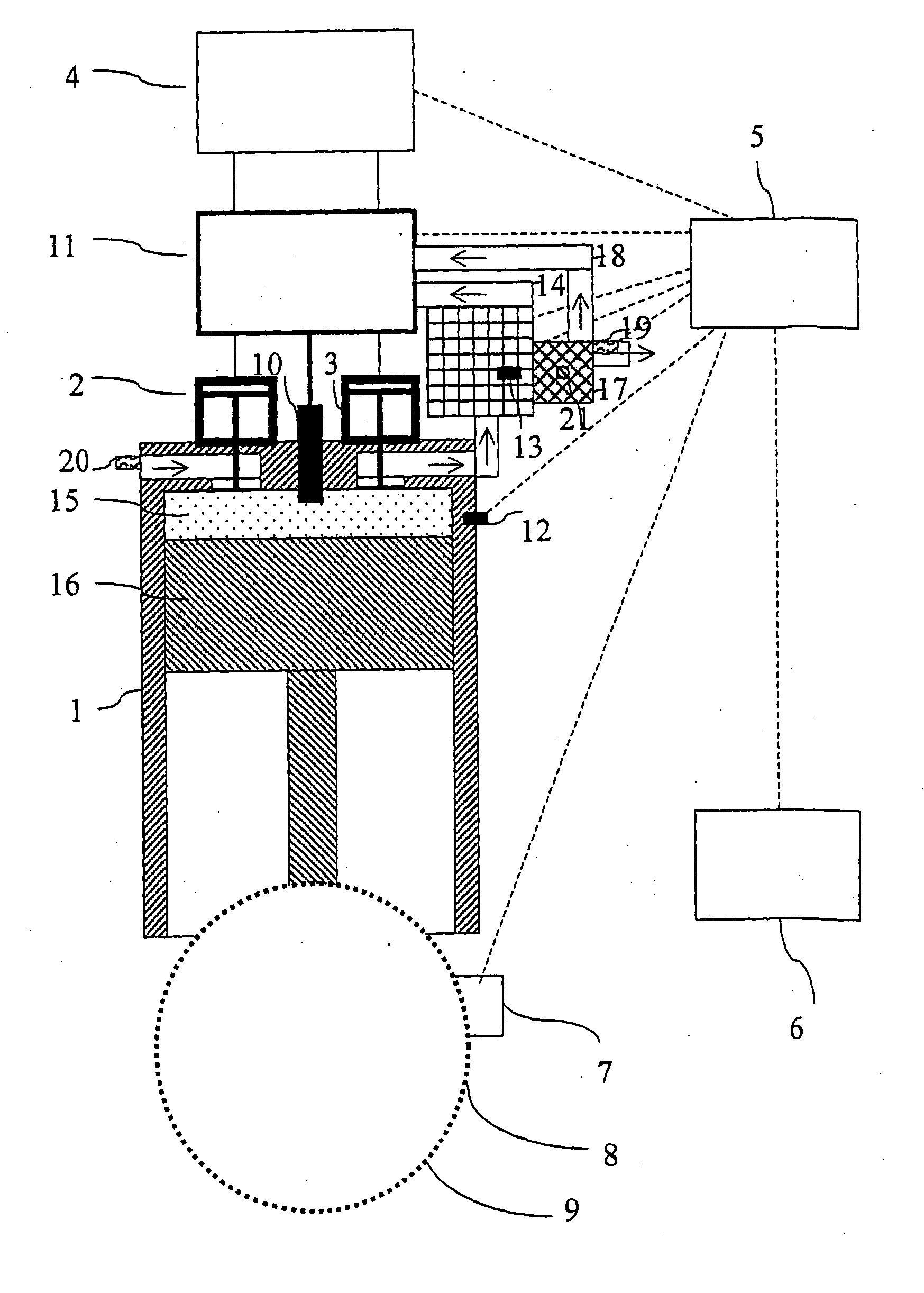
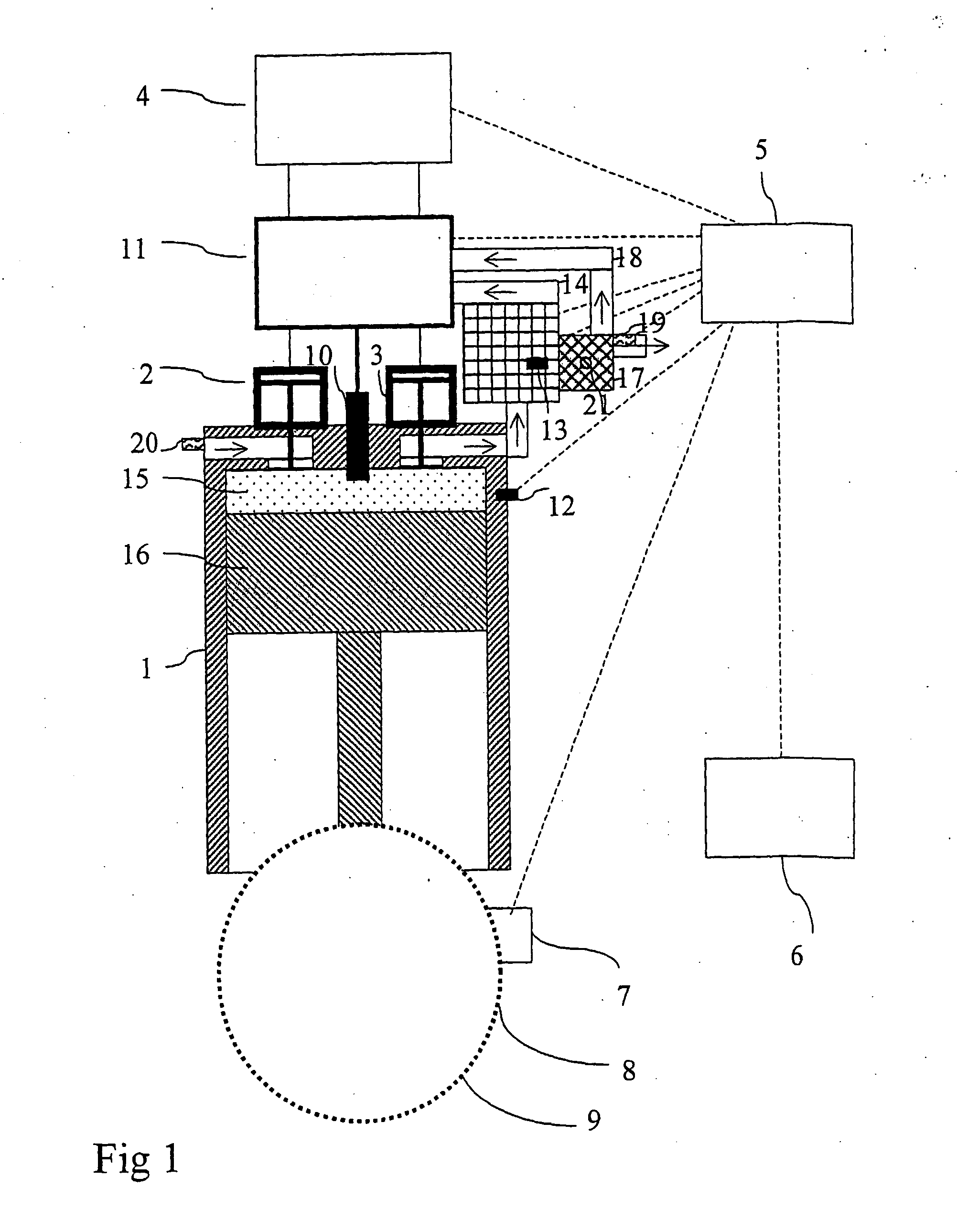
[0029]FIG. 1 is an exemplifying, schematic picture of a device according to the invention, showing a cylinder 1 with a piston 16. The device comprises an inlet valve 2 and an outlet valve 3 that are constituted by controllable valves, both of which, for the moment, are closed after an evacuation stroke that has just been ended. The piston 16 has reached its upper dead point. Water has been supplied to the combustion chamber 15 by means of the injection valve 10, in order to cool the surfaces that surround the combustion chamber 15, and an evaporation and pressure increase is taking place before a steam expansion stroke. A circuit 4 is used for the activation of the valves 2 and 3. A control unit 5 is operatively connected with the circuit 4 for signal-control of the circuit and the valves 2 and 3 that are connected with the circuit. A member 6, for example a gas pedal, is operatively connected with the control unit 5 for the purpose of torque commanding. A gauge 7, provided on a gra...


PUM


Abstract

A method for controlling an internal combustion engine, and an internal combustion engine, having at least one cylinder (1), a reciprocating piston (16) arranged in the cylinder (1), a combustion chamber (15) delimited by the cylinder (1) and the piston (16), and inlet and outlet valves (2, 3) that are controlled by a computer-based control system (5). The combustion engine includes elements (10) for injecting water or water steam into the combustion chamber (15), and the control system (5) is arranged to control the inlet and outlet valves (2, 3) and the elements (10) for injection of water or water steam such that power strokes that are mainly based on expanding combustion gases are alternated with power strokes that are mainly based on expanding water steam.

Description

FIELD OF THE INVENTION [0001] The present invention relates to a method for internal combustion engines with controllable valves, by which heat that, in engines of today, is lost through cylinder cooling and via exhaust gases is transformed into work. [0002] The invention also relates to a combustion engine comprising at least one cylinder, a reciprocating piston that is arranged in the cylinder, a combustion chamber that is delimited by the cylinder and the piston, and inlet and outlet valves that are controlled by a computer-based control system. Preferably, the control system is a control system based on a computer program and may be electrical or optical. [0003] The invention is also applicable to internal combustion engines regardless of type of combustion cycle. Otto-, Diesel-, Wankel-, HCCI and Free-piston engines are examples by which the invention is useful. However, the engines must be provided with controllable valves and equipment for injection of water and / or water stea...

Claims


Application Information

Patent Timeline
IPC IPC(8): F02B77/11F01B17/04F02B1/00F02B1/04F02B1/12F02B3/06F02B41/00F02B47/02F02D13/02F02D19/12F02D45/00F02G5/00
CPCF01B17/04Y02T10/20F01N5/02F02B1/04F02B1/12F02B3/06F02B41/00F02B47/02F02D13/0215F02G5/00F02M25/03Y02T10/121Y02T10/18Y02T10/16Y02T10/166F01N3/005Y02T10/12F02B75/02
Inventor HEDMAN, MATS
Owner CARGINE ENG AB
Why Eureka
Try Eureka