Apparatus and method for placing suture wires into tissue for the approximation and tensioning of tissue

Inactive Publication Date: 2005-02-17
DVL ACQUISITION SUB
View PDF98 Cites 55 Cited by
  • Summary
  • Abstract
  • Description
  • Claims
  • Application Information

AI Technical Summary

Problems solved by technology

However, conventional suturing requires a substantial amount of manipulation, i.e., the needle must be moved safely into position at the surgical site, then the needle (and trailing suture) must be passed through the target tissue, then the needle must be safely removed from the surgical site, and finally the suture must be effectively knotted.
This can be difficult and time-consuming to do.

Method used


Image

  • Apparatus and method for placing suture wires into tissue for the approximation and tensioning of tissue
  • Apparatus and method for placing suture wires into tissue for the approximation and tensioning of tissue
  • Apparatus and method for placing suture wires into tissue for the approximation and tensioning of tissue

Examples


Embodiment Construction

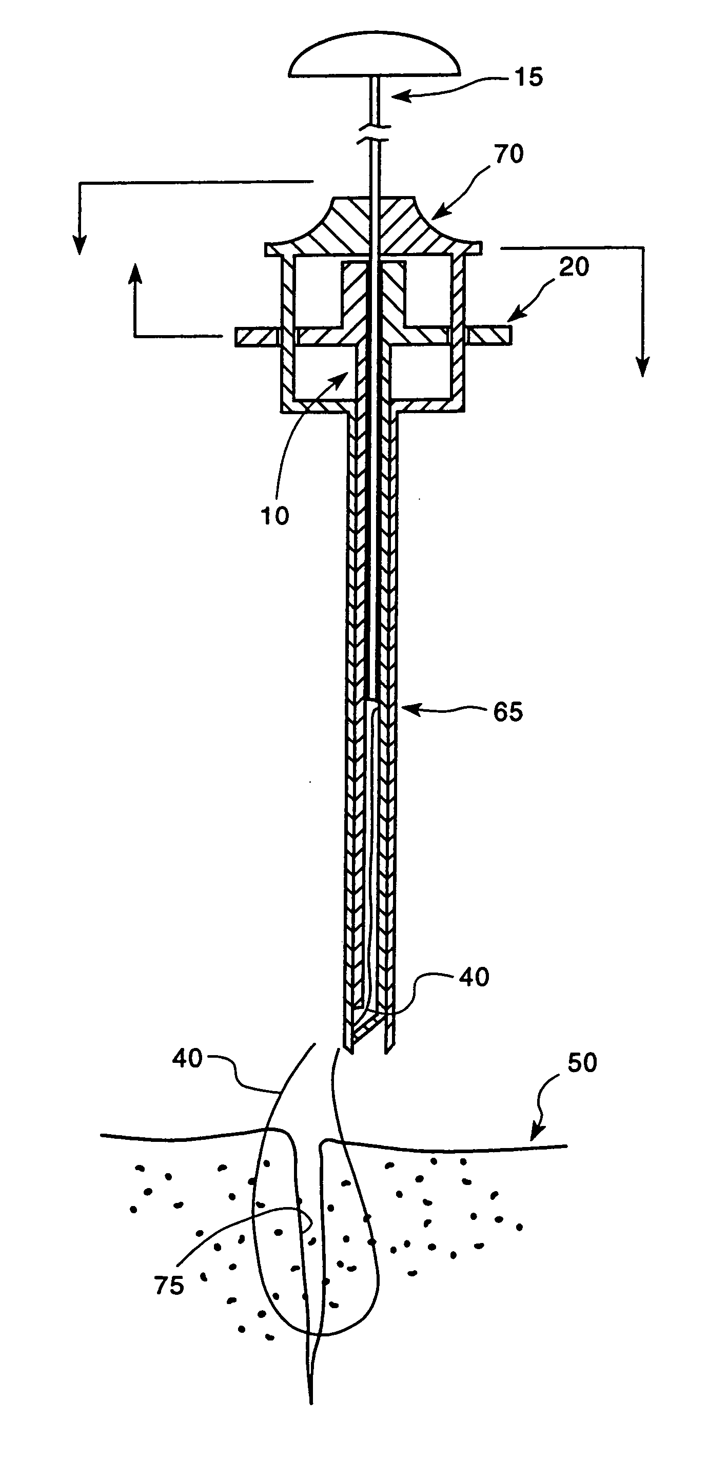
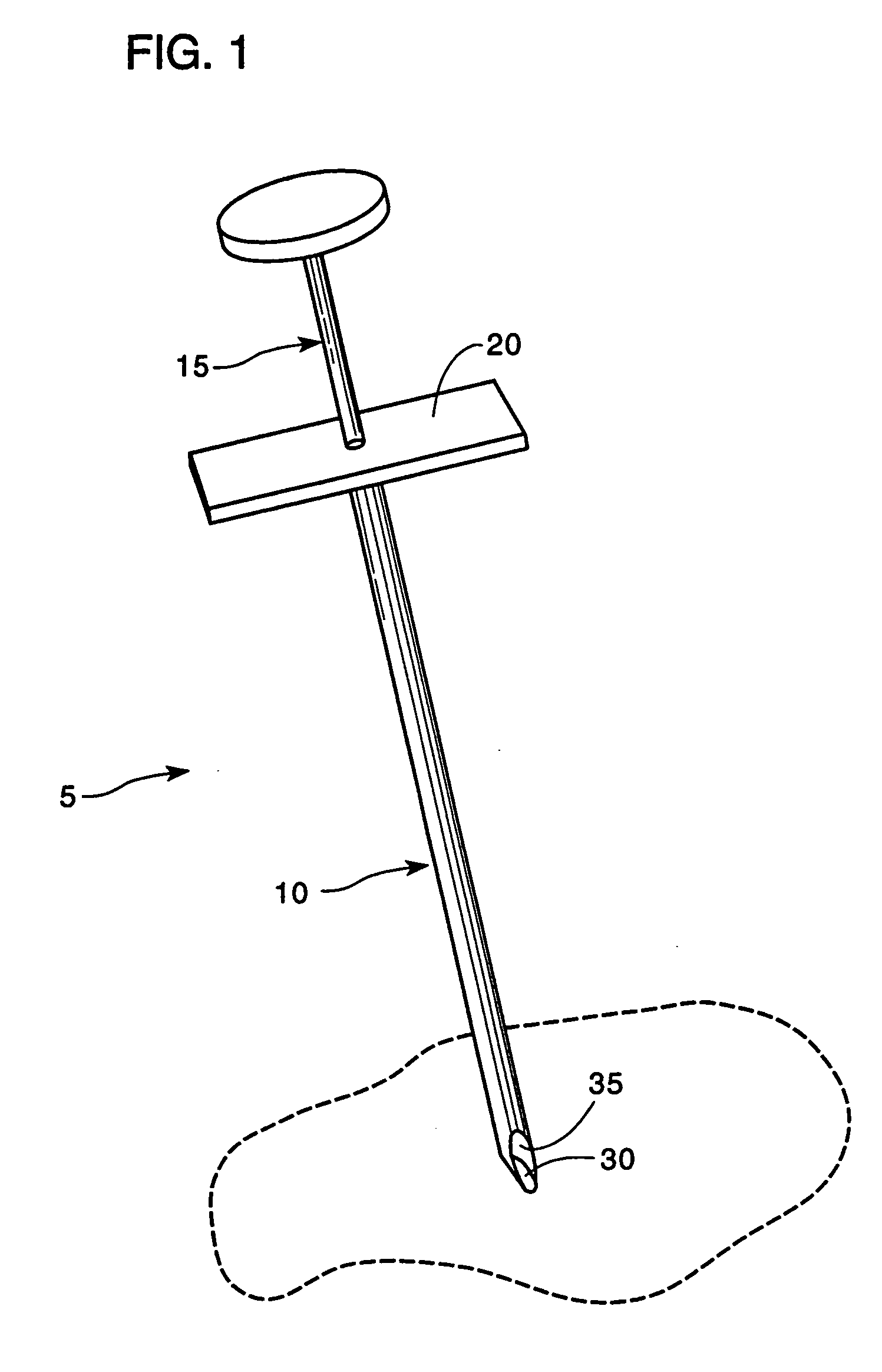
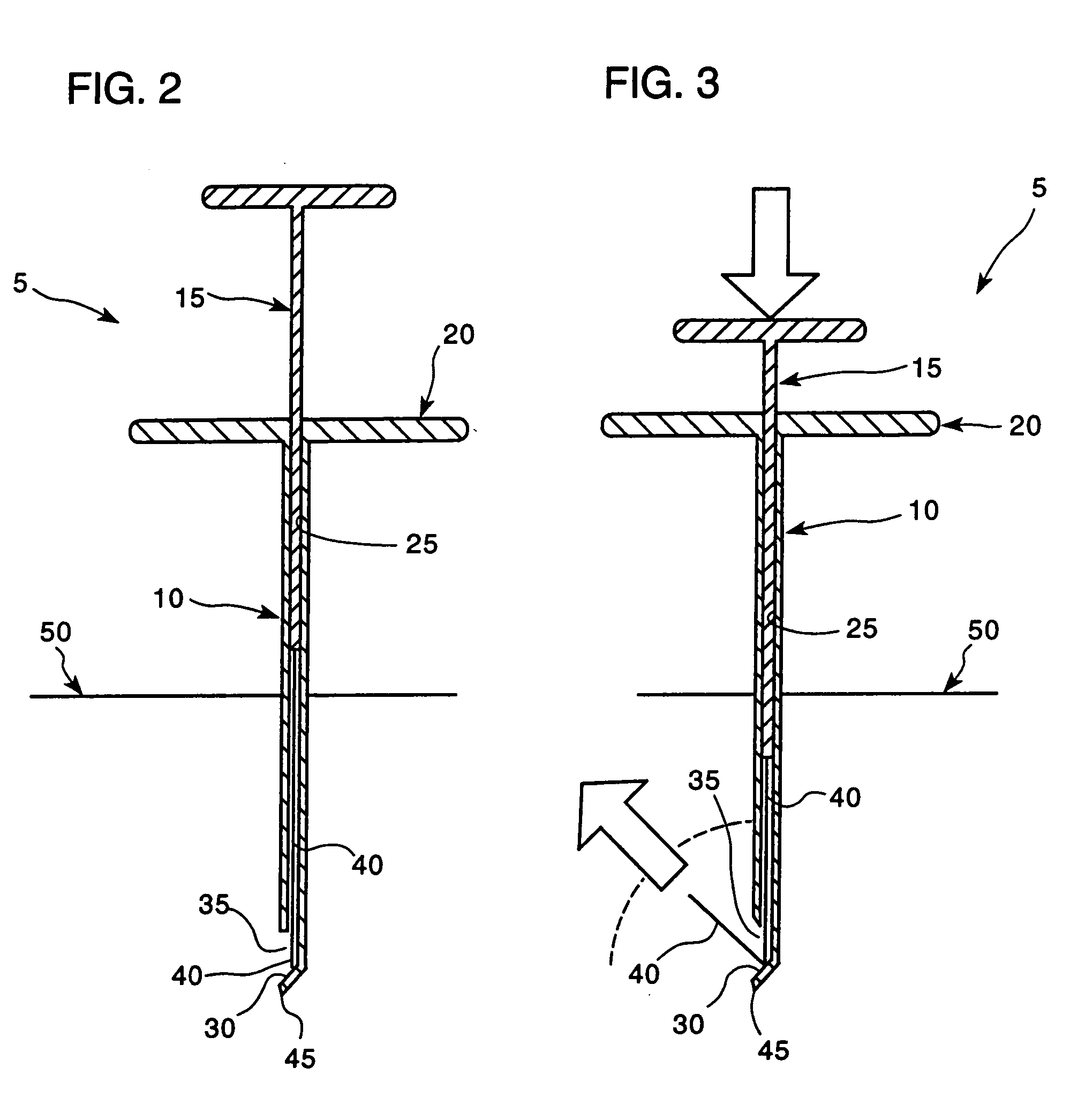
[0021] Looking first at FIGS. 1-3, there is shown a suture placer 5 formed in accordance with the present invention. Suture placer 5 generally comprises an elongated shaft 10 and a plunger 15. Shaft 10 has a crosshandle 20 at its proximal end, and contains a lumen 25 that runs from the proximal end of the shaft to a location near the distal end of the shaft.

[0022] At a location near the distal end of shaft 10, lumen 25 turns at a deflection die 30 and then proceeds out of the shaft through a side hole 35. Deflection die 30 is designed to turn a suture wire 40, passing distally down lumen 25, outward and backward (i.e., proximally). As a result, when the shaft's sharp distal tip 45 is placed in tissue 50, suture wire 40 travels below the surface of tissue 50 inside lumen 25 and, when the suture wire hits deflection die 30, the suture wire is deflected outward, through side hole 35, and backward up to the surface of tissue 50.

[0023] The shape of deflection die 30 helps determine the...


PUM


Abstract

A suture placer for placing a length of suture wire through tissue such that the suture wire is directed into the tissue and then back out again.

Description

REFERENCE TO PENDING PRIOR PATENT APPLICATION [0001] This patent application claims benefit of pending prior U.S. Provisional Patent Application Ser. No. 60 / 163,808, filed Nov. 15, 1999 by Gregory E. Sancoff et al. for DEVICE FOR PLACING SUTURE WIRES INTO TISSUE FOR APPROXIMATION AND TENSION, which pending prior patent application is hereby incorporated herein by reference.FIELD OF THE INVENTION [0002] This invention relates to surgical apparatus and methods in general, and more particularly to apparatus and methods for placing suture wires into tissue for the surgical approximation and tensioning of tissue. BACKGROUND OF THE INVENTION [0003] There is a growing trend to perform many surgical procedures using minimally invasive techniques. In such surgery, which is sometimes referred to as “keyhole surgery”, surgical instruments are inserted into the body through small surface incisions, and then the instruments are manipulated from outside the body while the actual surgery is carrie...

Claims


Application Information

Patent Timeline
IPC IPC(8): A61B17/04A61B17/06
CPCA61B17/0467A61B17/0469A61B2017/06052A61B17/068A61B2017/0498A61B17/0482
Inventor SANCOFF, GREGORY E.FIELD, FREDERIC P.
Owner DVL ACQUISITION SUB
Why Eureka
Try Eureka