Device and method for trenchless replacement of underground pipe

a technology for underground pipes and devices, applied in the direction of tube shearing machines, manufacturing tools, borehole/well accessories, etc., can solve the problems of heavy equipment, high price, and limited use of prior art trenchless technology

Inactive Publication Date: 2005-02-24
CARTER ROBERT WARD +1
View PDF61 Cites 11 Cited by
  • Summary
  • Abstract
  • Description
  • Claims
  • Application Information

AI Technical Summary

Benefits of technology

[0011] The components of the present invention can be easily built in several sizes according to the strength of the cable to be pulled, and componentized, so that no component weighs more than 75 lbs. One may can now move all the equipment necessary to pull up to 150,000 pounds (75 tons), in one average sized pick-up truck and hand carry it to remote areas normally inaccessible to the larger prior art equipment. The present invention has particular applications in the vast 4Δ diameter home lateral pipe field, which has, up to now been relatively untouched by the trenchless method of pipe replacement.

Problems solved by technology

This standard equipment for this technology is very large, heavy, and therefore requires additional large, heavy duty equipment for the transportation to, and the placement thereof on site, and the operation thereof on site.
They also need large excavations, such that the support equipment can take up enough room so as to create traffic problems and even require street closures.
This also means that only large companies with large financial resources can afford the equipment necessary to replace underground pipes, and because the costs and maintenance on this equipment can be high, their prices are also high.
Therefore the use of this prior art trenchless technology has been limited mainly to the 6 inch or above size pipe of municipal or corporate supply and sewer lines, and is used mainly by large contractors.

Method used


Image

  • Device and method for trenchless replacement of underground pipe
  • Device and method for trenchless replacement of underground pipe
  • Device and method for trenchless replacement of underground pipe

Examples


Embodiment Construction

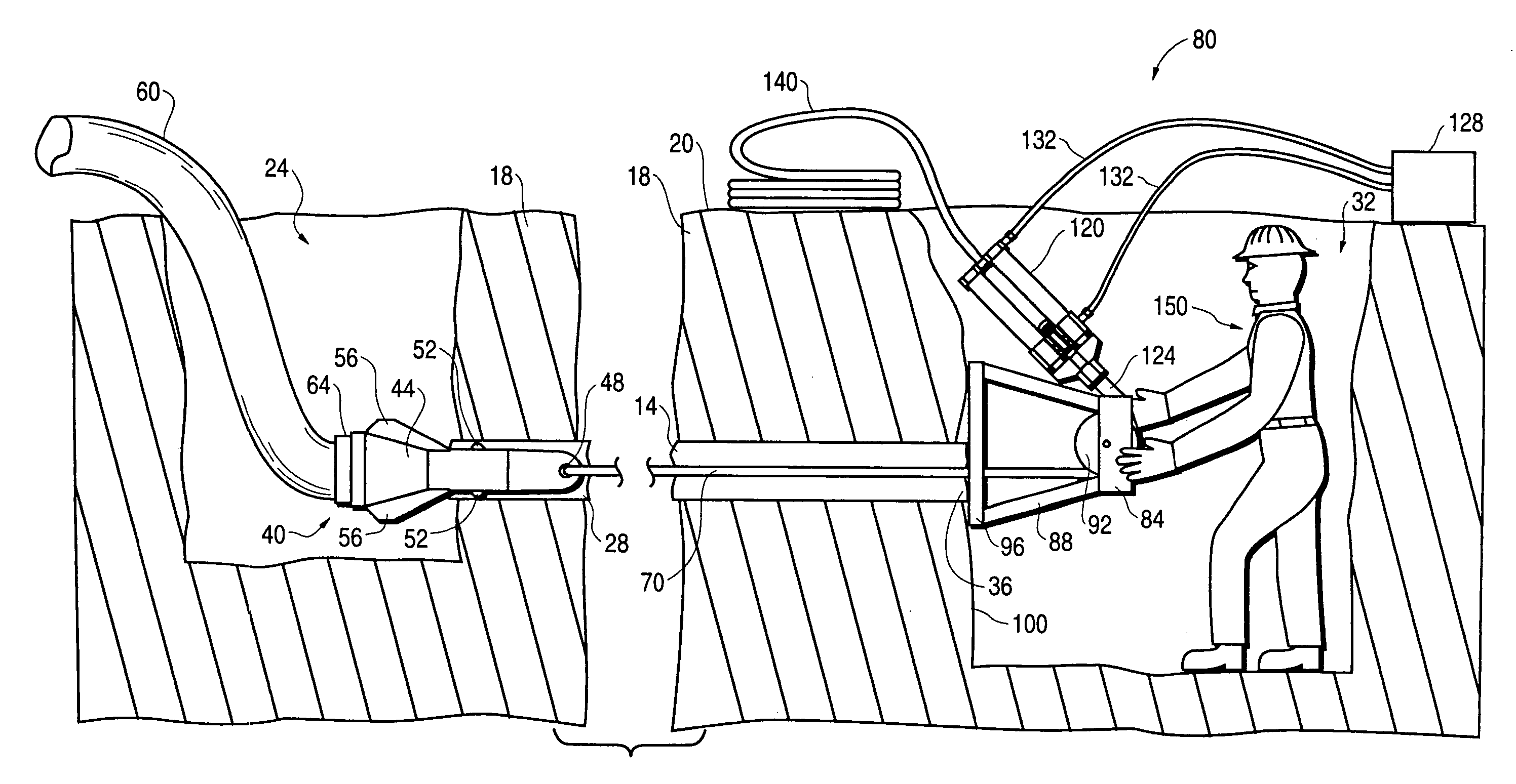
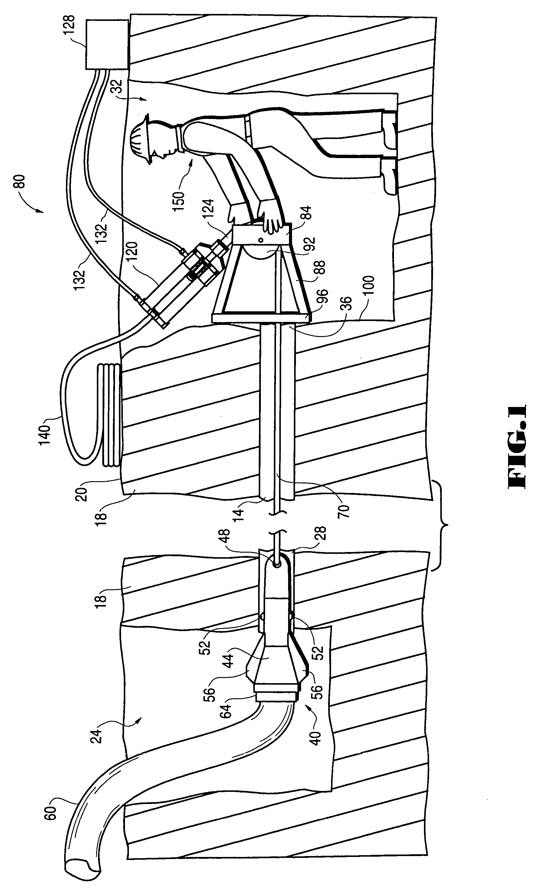
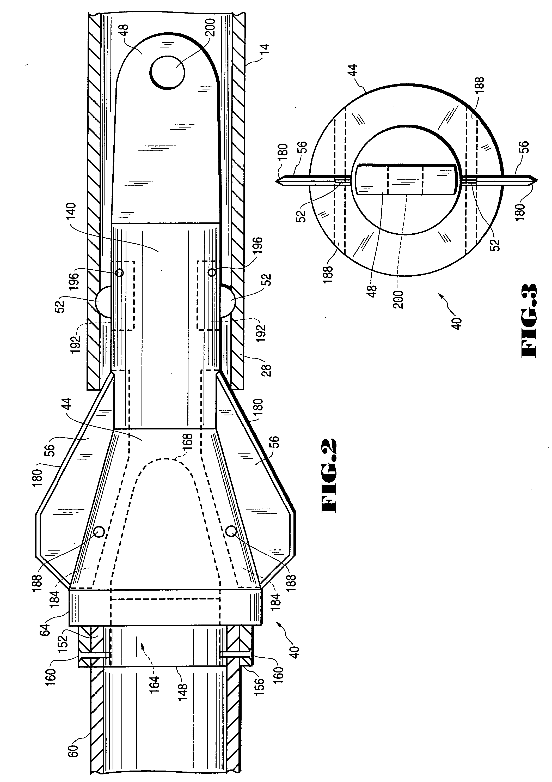
[0046]FIG. 1 is a side elevational view depicting the use of the trenchless pipe replacement device of the present invention. As depicted therein, an existing pipe 14 that is being replaced is disposed within earth 18 beneath the ground level surface 20. A first hole 24 has been dug to reveal a first end 28 of the pipe 14, and a second hole 32 has been dug to reveal a second end 36 of the pipe 14. A pipe parting and expanding device 40 referred to herein as a mole, is inserted within the first pipe end 28. The mole 40 includes a generally tapered body portion 44, a nose portion 48, one or more pipe scoring wheels 52 and one or more pipe parting fins or blades 56 disposed along the body portion 44. A length of replacement pipe 60 is removably engaged to the rearward end 64 of the body portion 44 of the mole 40. A detailed description of the mole 40 is presented herebelow.

[0047] A mole pulling cable 70 is passed from the second end of the pipe 36, through the pipe 14 to a pinned enga...


PUM

PropertyMeasurementUnit
sizeaaaaaaaaaa
sizeaaaaaaaaaa
sizeaaaaaaaaaa

Abstract

The basic features of the invention include a pipe parting mole, a length of cable that is engagable to the mole, a cable pulling device and a cable pulling device engagement means that provides a mounting structure for the cable pulling device. The cable pulling device engagement means generally includes a reaction plate and a structure for removably engaging the cable pulling device therewithin. A cable pulling frame may be advantageously used to facilitate the removal of the cable from a relatively small hole that is created at the pulling end of the pipe.

Description

CROSS-REFERENCE TO RELATED APPLICATIONS [0001] The present invention is a continuation application of copending U.S. patent application Ser. No. 10 / 337,934, filed Jan. 6, 2003, which is a continuation U.S. patent application Ser. No. 09 / 939,084 (U.S. Pat. No. 6,524,031) filed Aug. 24, 2001, which is a continuation of U.S. patent application Ser. No. 09 / 350,948 (U.S. Pat. No. 6,305,880), filed Jul. 9, 1999, which is a continuation-in-part application, based upon and claiming priority to pending International Patent Application Serial No. PCT / US98 / 00266, filed Jan. 9, 1998 by the inventors hereof; which application claims priority to U.S. Provisional Patent Application Ser. No. 60 / 035,174, filed Jan. 9, 1997 by the inventors hereto to which priority is claimed.BACKGROUND OF THE INVENTION [0002] 1. Field of the Invention [0003] The present invention relates generally to devices and methods for the trenchless replacement of underground pipes and more particularly to pipe splitting devic...

Claims


Application Information

Patent Timeline
Patent Type & Authority Applications(United States)
IPC IPC(8): B23D21/02B23D21/14E03F3/06E21B7/20E21B7/30E21B29/10F16L1/00F16L1/024
CPCB23D21/02E03F3/06E03F2003/065F16L55/1658E21B7/30E21B29/10E21B7/205
Inventor CARTER, ROBERT WARDCARTER, ROBERT WILLIAMS
Owner CARTER ROBERT WARD
Why Eureka
Try Eureka