Electrical connector

Inactive Publication Date: 2005-02-24
HON HAI PRECISION IND CO LTD
View PDF4 Cites 12 Cited by
  • Summary
  • Abstract
  • Description
  • Claims
  • Application Information

AI Technical Summary

Benefits of technology

[0005] An object, therefore, of the invention is to provide an improved electrical connector which is capable of co

Problems solved by technology

However, said mating electrical connector only can downwardly press the probe pin, if a mating electrical connector is pushed to contact with side wall of the vertically standing probe pin in a side to side direction, the

Method used


Image

  • Electrical connector
  • Electrical connector
  • Electrical connector

Examples


Example

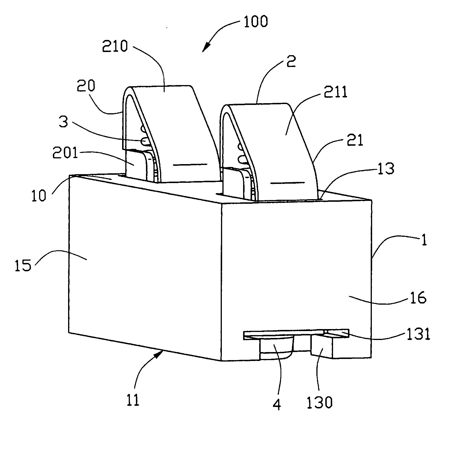
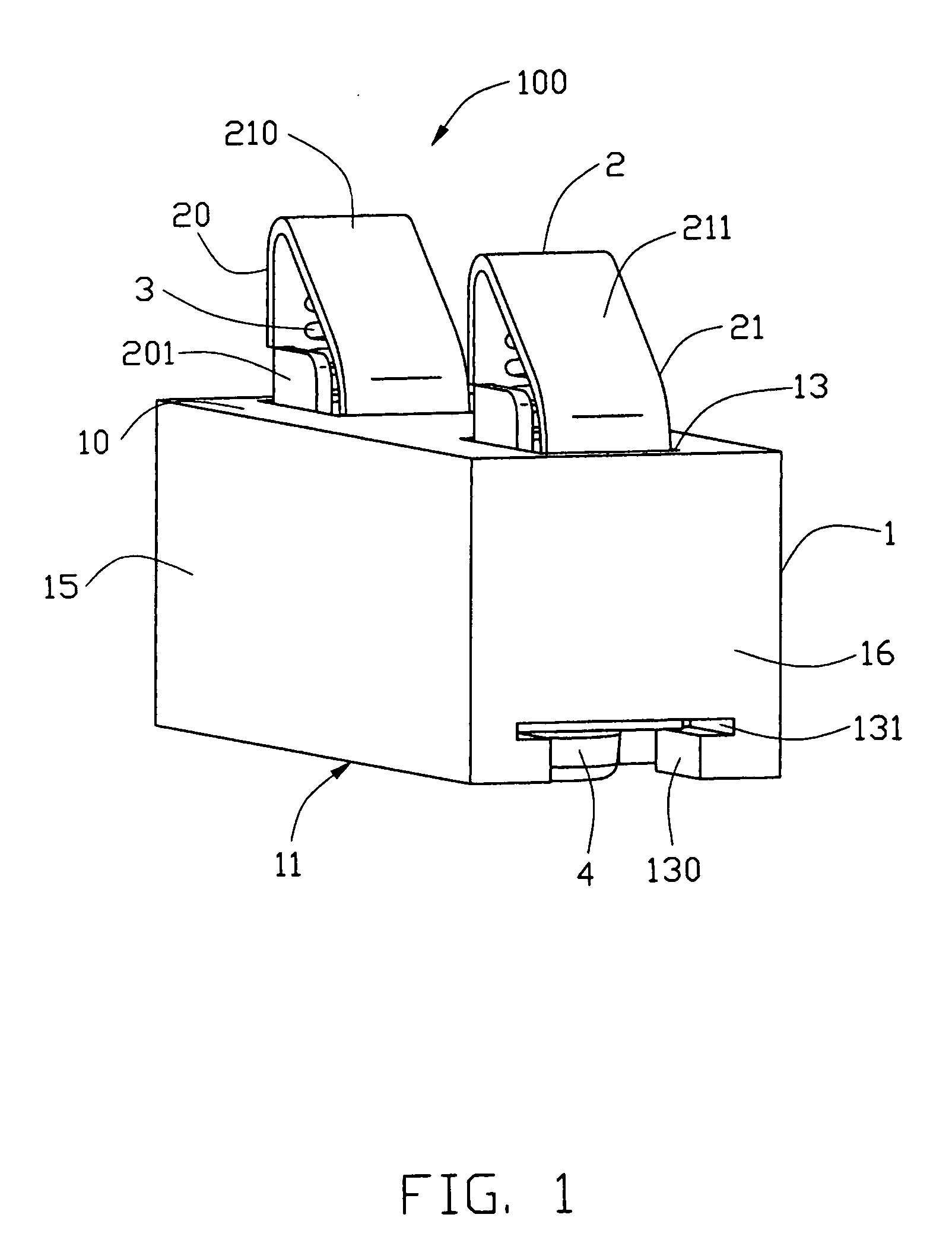
[0013] Referring to FIGS. 1-4, the present invention 100 includes an insulative housing 1, a pair of contact terminals 2 retained in the housing 1, a pair of spring terminals 3 and a pair of retaining contacts 4.

[0014] Referring to FIG. 4, the insulative housing 1 is substantially rectangular and includes a top wall 10, a bottom wall 11, a longitudinally extending front wall 14, an opposite rear wall 15 and opposite side walls 16. A pair of through holes (passageways) 13 is defined through the top and the bottom walls 10, 11 and is adjacent to corresponding side walls 16 of the housing 1. Two pairs of slots 133 extend through the bottom wall 11 and are respectively adjacent to the front and rear walls 14, 15. Each pair of slots 133 is opposite to each other and communicates with a corresponding through hole 13. A projecting portion 134 downwardly projects into each slot 133 from the top wall 10. A pair of U-shaped gaps 130 is longitudinally defined in the bottom wall 11. Each gap 1...


PUM


Abstract

An electrical connector (100) includes an insulative housing (1), a pair of contact terminals (2) mounted on the housing, a pair of spring terminals (3) and a pair of retaining contacts (4). The insulative housing defines a receiving space for receiving the contact terminals and spring terminals through a top and bottom wall (10, 11) thereof. Each contact terminal includes a body portion (20), a cantilevered beam (21) and a contact portion (210) interconnecting top portions of body portion and cantilevered beam. The cantilevered beam downwardly and angularly extends from the contact portion. The cantilevered beam has a leading face (211) projecting beyond the top wall of the housing. Each spring terminal is retained between the contact terminal and the retaining contact. A mating electrical connector can upwardly slide along the leading face to electrically connect with the contact terminals by the leading surface.

Description

BACKGROUND OF THE INVENTION [0001] 1. Filed of the Invention [0002] The present invention generally relates to an electrical connector and more particularly, to an electrical connector mounted on a printed circuit board. [0003] 2. Description of the Prior Art [0004] Probe pin has been designed into connectors for the purpose of contacting with mating electrical connector, as is disclosed in U.S. Pat. No. 6,340,320 B1. In this patent, the probe pin vertically stands in an insulative housing and comprises a lower end standing in an upright sleeve enclosed by the insulative housing and an upper end upwardly exposed to outside of the housing. A coiled spring is assembled into the upright sleeve, with an upper end thereof supporting the lower end of the probe pin, and with a lower end thereof pressing a cover plate, which is located in a bottom portion of the sleeve, thereby providing the probe pin with flexibility. In use, a mating electrical connector (battery, memory card or printed c...

Claims


Application Information

Patent Timeline
IPC IPC(8): H01R13/24
CPCH01R13/2421
Inventor ZHENG, QISHENGDU, SHAOPING
Owner HON HAI PRECISION IND CO LTD
Why Eureka
Try Eureka