Economizer chamber for minimizing pressure pulsations

a technology of economizer chamber and economizer chamber, which is applied in the direction of fluid circulation arrangement, refrigeration machine, lighting and heating apparatus, etc., can solve the problems of failure of the float valve located in the economizer chamber, subject to these pulsations, etc., and achieve the effect of minimizing pressure pulsations

Inactive Publication Date: 2005-03-03
CARRIER CORP
View PDF3 Cites 11 Cited by
  • Summary
  • Abstract
  • Description
  • Claims
  • Application Information

AI Technical Summary

Benefits of technology

[0005] Accordingly, it is an object of the present invention to provide a baffle for use in an economizer chamber for minimizing pressure pulsations.

Problems solved by technology

The float valve located in the economizer chamber is subjected to these pulsations and can experience failure.

Method used


Image

  • Economizer chamber for minimizing pressure pulsations
  • Economizer chamber for minimizing pressure pulsations
  • Economizer chamber for minimizing pressure pulsations

Examples


Embodiment Construction

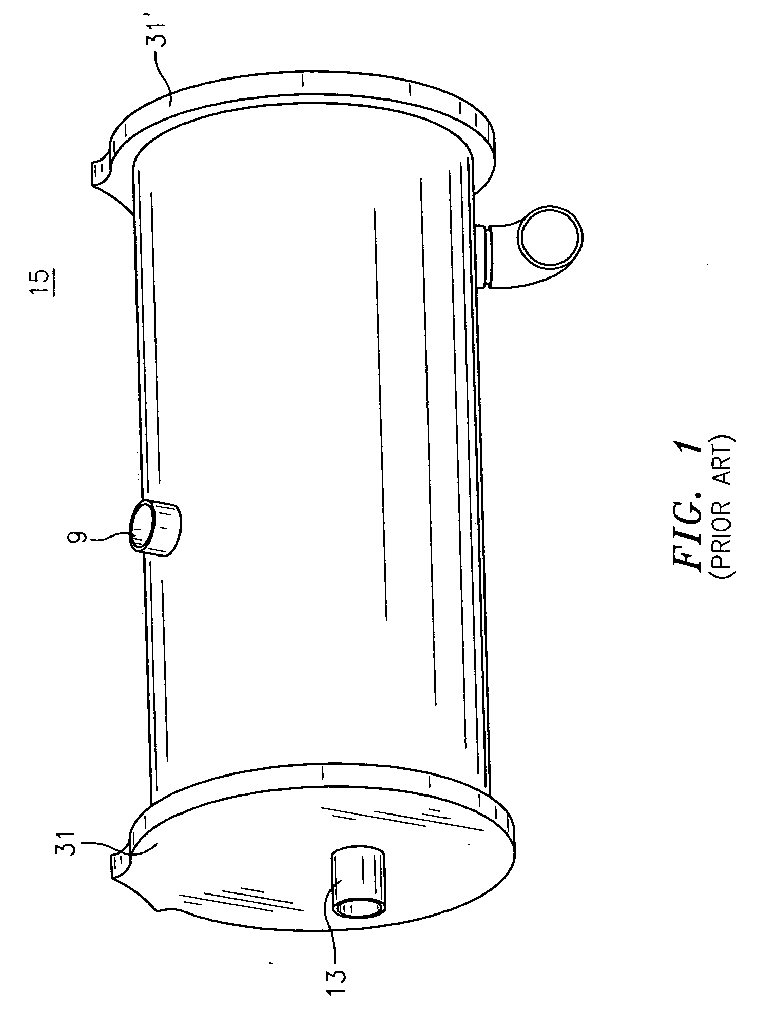
[0012] It is therefore a central purpose of the present invention to provide a baffle for use in an economizer which serves to substantially reduce in intensity the magnitude of the pulsations experienced by a float valve. With reference to FIG. 1, there is illustrated an economizer 15 known in the art. The economizer 15 is substantially cylindrical in nature terminated at both ends by end plates 31, 31′. Extending through one of the end plates 31 is spray pipes 13 which transmits fluid and gas from the condenser. Exiting from the body of the economizer 15 is discharge pipe 9. Discharge pipe 9 carries gas to the compressor.

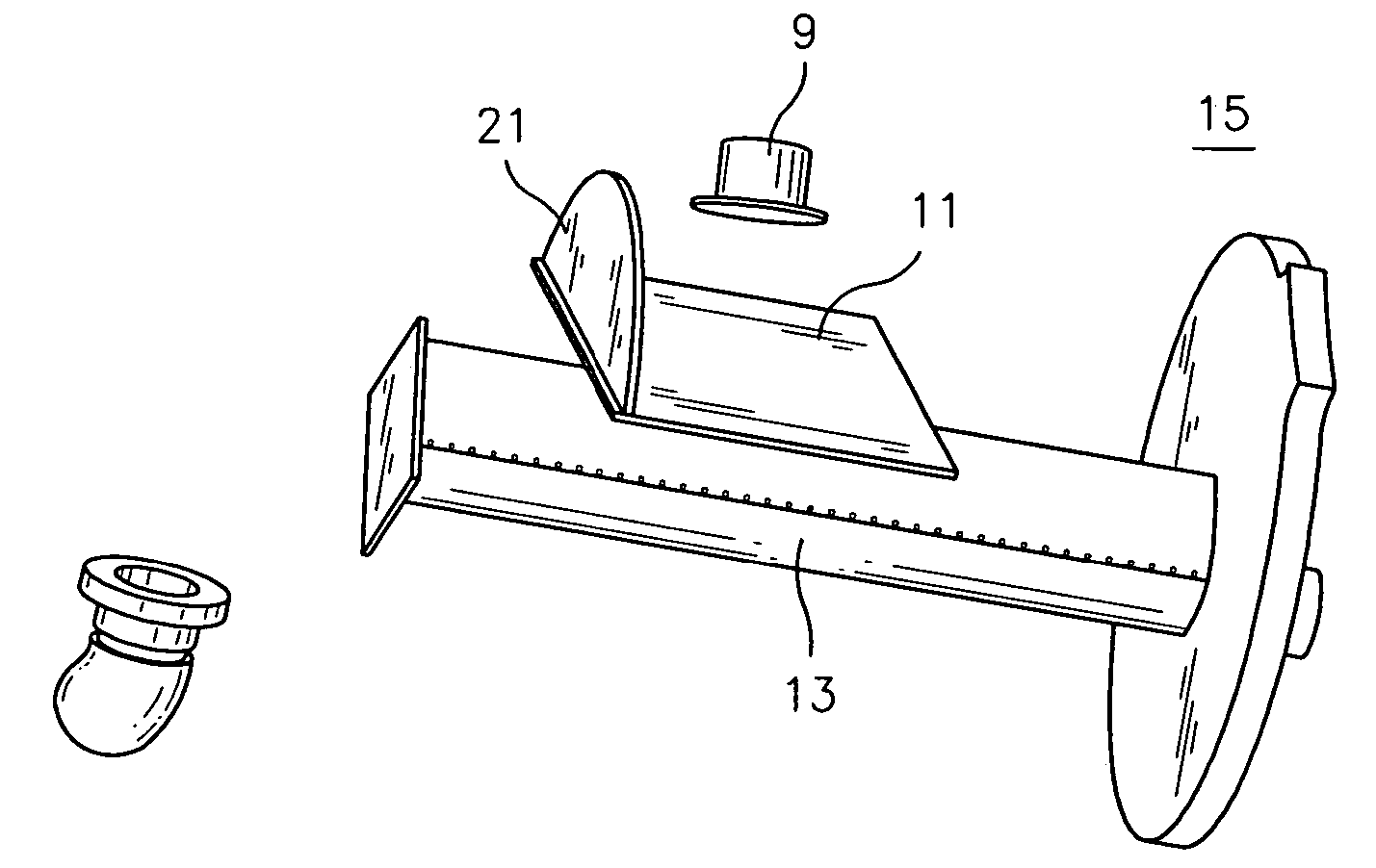
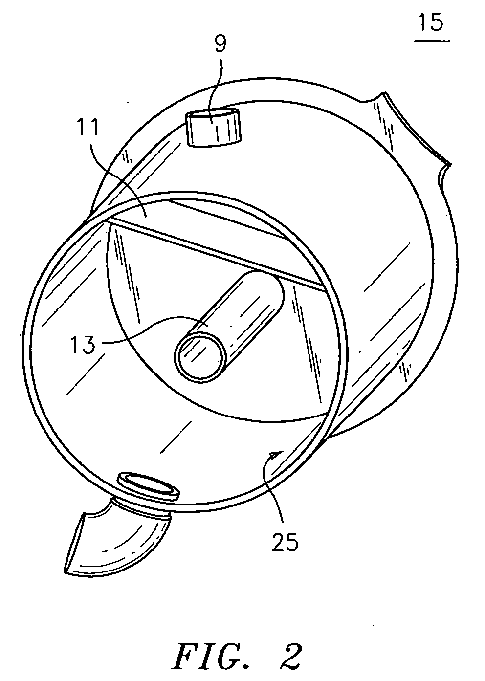
[0013] With reference to FIG. 2, there is illustrated the inside of an economizer 15 of the present invention showing more clearly the composition of the spray pipe 13. As is evident, spray pipe 13 extends in a direction generally perpendicular to either one of the end plates 31, into the interior cavity of the economizer 15 bonded by the inner surface 25 of the ...


PUM


Abstract

A baffle for use in a refrigerator apparatus comprises a baffle plate comprising a first and a second opposing sides attached to an inner surface of the refrigerator apparatus, a baffle seal plate attached along a third side of the baffle plate, the baffle plate seal plate attached to the inner surface of the refrigerator apparatus.

Description

BACKGROUND OF THE INVENTION [0001] (1) Field of the Invention [0002] The present invention relates to baffle assembly for use in an economizer chamber for minimizing pressure pulsations. [0003] (2) Description of the Related Art [0004] Float valves are typically used in water cooled chillers to maintain a liquid seal and for controlling coolant flow to the evaporator. In screw chillers, capacity and performance are improved through the use of an economizer cycle. During such a cycle, the economizer flow is introduced into the screw compressor chamber between inlet and outlet ports. As the screw compressor is a positive displacement compressor, it produces high pressure pulsations. The float valve located in the economizer chamber is subjected to these pulsations and can experience failure. What is therefore needed is a design of an economizer which minimizes the pressure pulsations experienced by the float valve. SUMMARY OF THE INVENTION [0005] Accordingly, it is an object of the pr...

Claims


Application Information

Patent Timeline
Patent Type & Authority Applications(United States)
IPC IPC(8): F25B41/06F25B43/00
CPCF25B41/065F25B2400/23F25B2400/13F25B43/006F25B41/315
Inventor SISHTLA, VISHNU M.
Owner CARRIER CORP
Why Eureka
Try Eureka