Inline high turbulence mixer having combined oblique and transverse stationary vanes

a stationary vanes and mixer technology, applied in the field of mixers, can solve the problems of mixer design not mixing well, need to add additional chemicals or accept less than desired mixing performance, and mixer effectiveness, and achieve the effects of minimizing pressure pulsation, high turbulence, and reducing mixing difficulty

Inactive Publication Date: 2005-04-19
ITT MFG ENTERPRISES LLC
View PDF13 Cites 3 Cited by
  • Summary
  • Abstract
  • Description
  • Claims
  • Application Information

AI Technical Summary

Benefits of technology

[0016]In operation, the transverse stationary vane near the inlet prevents the chemical from passing under the rotating vanes and helps to direct the chemical flow into the rotating vanes. As discussed above, the transverse inlet vane may be perpendicular or nearly perpendicular to the flow or may be angled to direct the chemical flow and minimize pressure pulsation to the process flow or may be angled to direct the chemical flow and minimize pressure pulsation that can lead to vibration.
[0017]Chemicals are injected upstream of the inline mixer and flow into the high turbulence mixer. The transverse inlet vane provides an initial zone of high turbulence. The transverse inlet vane also directs the chemicals into the mixer's highest turbulence zone (created by shear forces generated from rotating vanes passing the stationary vanes) and prevents the injected chemicals from flowing along the bottom of the mixer casing and bypassing the mixer rotor. The combination of initial high turbulence and directing of the chemical flow into the highest turbulence zone of the mixer improves mixing effectiveness, giving the same performance with less chemical addition.

Problems solved by technology

This flow bypass reduces the mixing effectiveness, causing non-uniform concentrations of chemical(s), resulting in the need to add additional chemicals or accept less than desired mixing performance.
However this mixer design does not mix well, i.e. the “mixing effectiveness” is not high enough.

Method used


Image

  • Inline high turbulence mixer having combined oblique and transverse stationary vanes
  • Inline high turbulence mixer having combined oblique and transverse stationary vanes
  • Inline high turbulence mixer having combined oblique and transverse stationary vanes

Examples


Embodiment Construction

FIGS. 4–7: The Casing 100

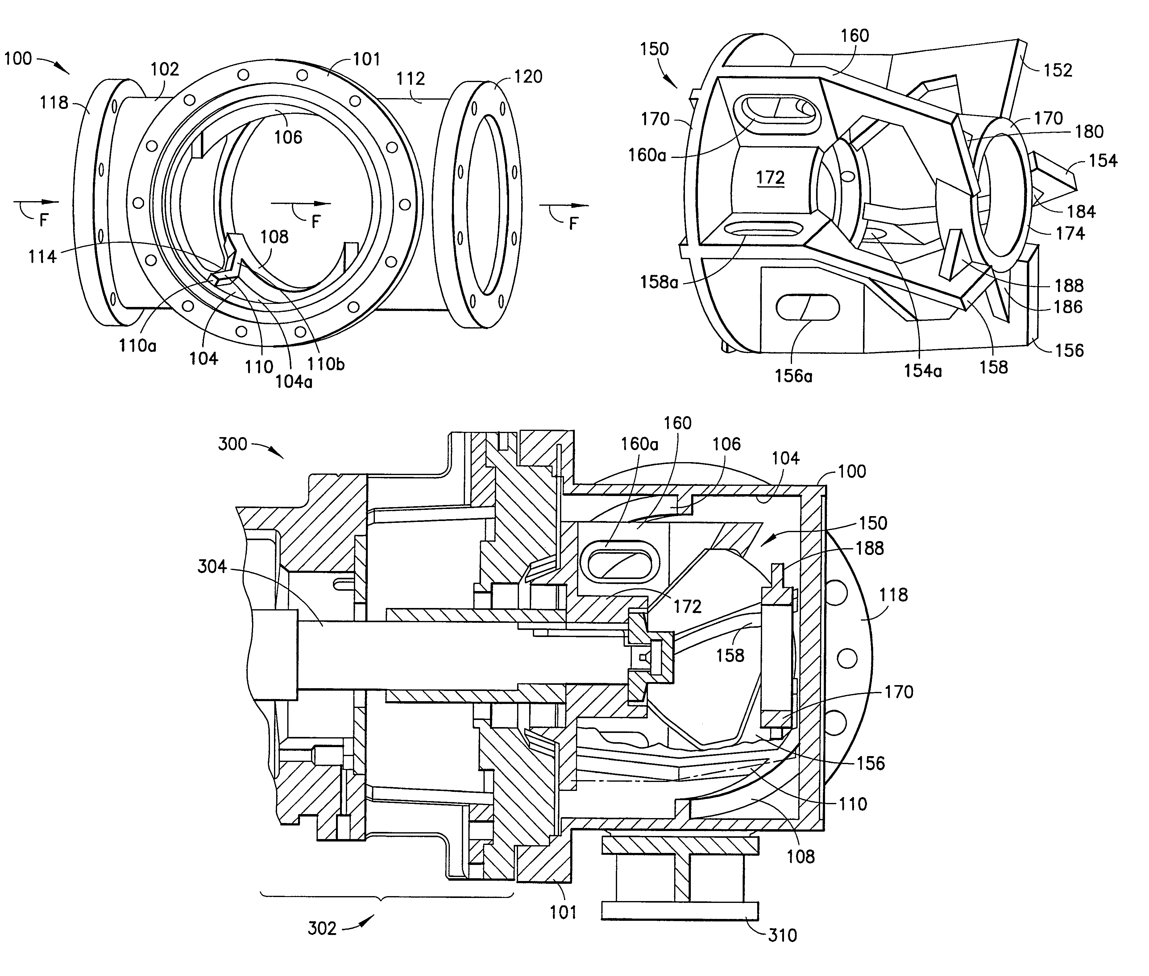
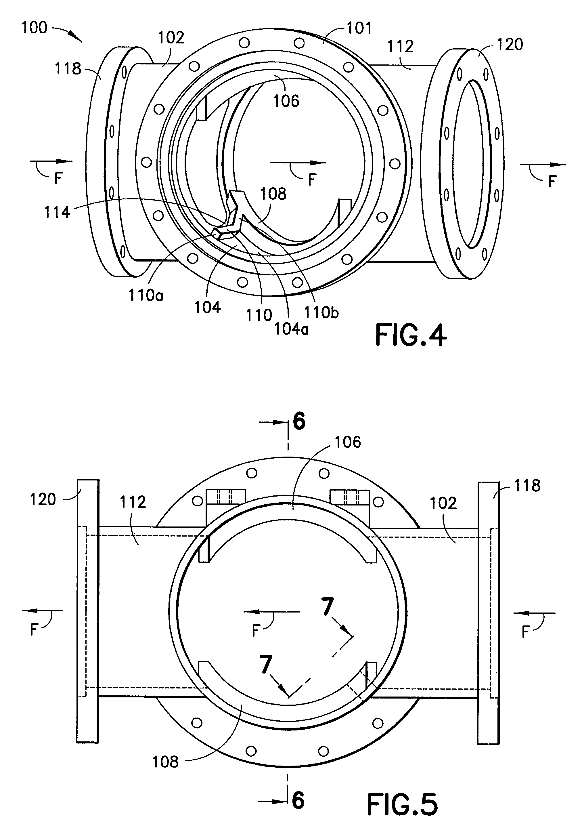
[0031]FIGS. 4–7 show a casing generally indicated as 100 of an inline mixer according to the present invention. The casing 100 has a flange for receiving a rotor assembly shown and described in relation to FIG. 11. Similar elements in FIGS. 4–7 and 11 are labelled with similar reference numerals.

[0032]FIG. 4 shows the casing 100 having an inlet generally indicated as 102 for receiving one or more chemicals and a process flow media, not shown, an inner surface 104 defining a cavity therein, one or more stationary vanes 106, 108 arranged obliquely on the inner surface 104 in relation to the direction of flow (which is generally indicated by flow arrows labelled F) of the chemical and process flow media, a transverse stationary vane 110 arranged on the inner surface 104 substantially perpendicular to the direction of flow F of the chemical and process flow media, and an outlet 112 for providing a mixture of the chemical and process flow media from the casing 1...


PUM


Abstract

An inline mixer has a casing and a rotor. The casing has an inlet for receiving a chemical and a process flow media, an inner surface defining a cavity therein, a stationary vane arranged obliquely on the inner surface in relation to the direction of flow of the chemical and process flow media, a transverse stationary vane arranged on the inner surface substantially perpendicularly in relation to the direction of flow of the chemical and process flow media, and an outlet for providing a mixture of the chemical and process flow media. The rotor is arranged in the cavity of the casing and has rotary vanes that rotatably cooperate with the stationary vane and the transverse stationary vane for mixing the chemical and process flow media. The transverse stationary vane is a straight or bent plate in relation to the direction of flow of the mixture.

Description

[0001]This application is a continuation of application Ser. No. 10 / 199,591, filed on Jul. 17, 2002, now abandoned.BACKGROUND OF THE INVENTION[0002]1. Field of Invention[0003]The present invention relates to a mixer; and more particularly relates to an inline mixer used to mix one or more chemicals with a process flow media.[0004]2. Description of Related Art[0005]Inline mixers, such as that shown in FIGS. 1–3, are used to mix one or more chemicals with a process flow media.[0006]FIG. 1 shows a casing 10 of one such known inline mixer having an inlet 12 for receiving the chemical and process flow media for mixing and an outlet 14 for providing a mixture thereof. The chemical is injected into the process flow upstream of the inline mixer. In FIGS. 1 and 3, the casing 10 has a stationary vane 18 that is a continuous vane arranged around and on an inner surface 10a of the casing 10 at an oblique angle relative to the direction of flow of the chemical and process flow media.[0007]FIG. 2...

Claims


Application Information

Patent Timeline
Patent Type & Authority Patents(United States)
IPC IPC(8): B01F7/00
CPCB01F7/0075B01F7/00908B01F2215/0422B01F27/27B01F27/50
Inventor CAPPELLINO, CHARLES A.PADDOCK, DOUGLAS
Owner ITT MFG ENTERPRISES LLC
Why Eureka
Try Eureka