

Sintering raw material mixing device for smelting
A technology of mixing and raw materials, applied in the field of smelting equipment, can solve the problems of cumbersome operation, poor mixing effect, time-consuming and labor-intensive mixing, etc.
- Summary
- Abstract
- Description
- Claims
- Application Information
AI Technical Summary
Problems solved by technology
Method used
Image

Examples
Embodiment 1
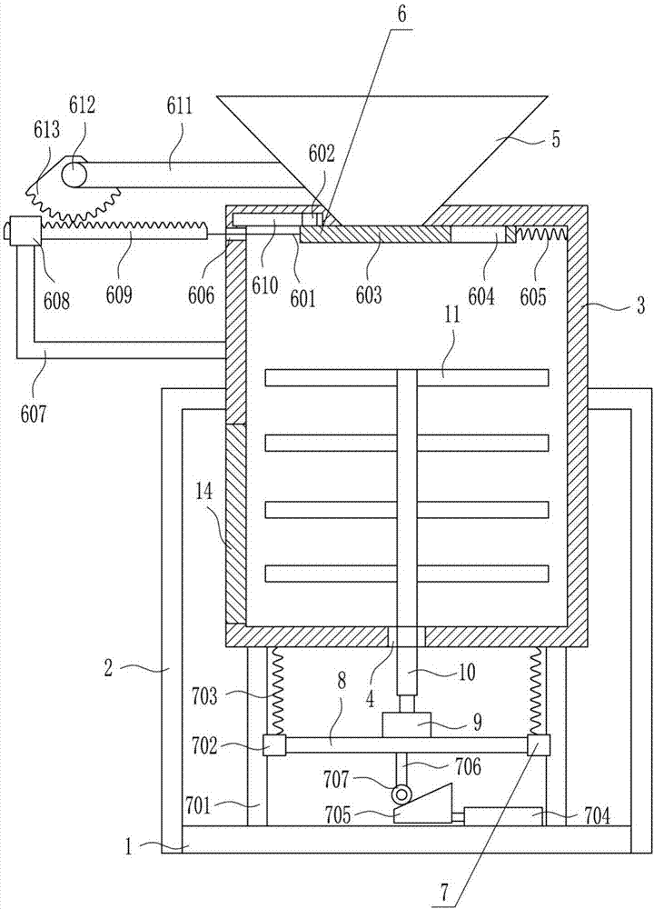
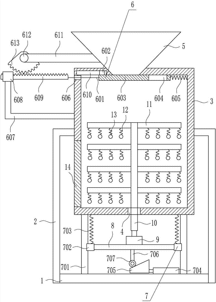
[0026] A mixing device for sintering raw materials for smelting, such as Figure 1-2As shown, it includes a base 1, a 7-shaped plate 2, a box body 3, a hopper 5, an intermittent feeding device 6, an up and down moving device 7, a mounting plate 8, a first motor 9, a rotating shaft 10, a stirring blade 11 and a box The door 14, the left side and the right side of the base 1 are connected with a 7-shaped plate 2 by bolts, and a box body 3 is connected by bolts between the two 7-shaped plates 2, and a guide hole 4 is opened in the middle of the bottom of the box body 3 , the lower left side of the box body 3 is provided with a box door 14, the top of the box body 3 is equipped with a lower hopper 5, the lower side of the lower hopper 5 is provided with an intermittent feeding device 6, and the top of the base 1 is provided with an up and down moving device 7 , a mounting plate 8 is connected to the up and down moving device 7, a first motor 9 is installed in the middle of the top...
Embodiment 2
[0028] A mixing device for sintering raw materials for smelting, such as Figure 1-2 As shown, it includes a base 1, a 7-shaped plate 2, a box body 3, a hopper 5, an intermittent feeding device 6, an up and down moving device 7, a mounting plate 8, a first motor 9, a rotating shaft 10, a stirring blade 11 and a box The door 14, the left side and the right side of the base 1 are connected with a 7-shaped plate 2 by bolts, and a box body 3 is connected by bolts between the two 7-shaped plates 2, and a guide hole 4 is opened in the middle of the bottom of the box body 3 , the lower left side of the box body 3 is provided with a box door 14, the top of the box body 3 is equipped with a lower hopper 5, the lower side of the lower hopper 5 is provided with an intermittent feeding device 6, and the top of the base 1 is provided with an up and down moving device 7 , a mounting plate 8 is connected to the up and down moving device 7, a first motor 9 is installed in the middle of the to...
Embodiment 3
[0031] A mixing device for sintering raw materials for smelting, such as Figure 1-2 As shown, it includes a base 1, a 7-shaped plate 2, a box body 3, a hopper 5, an intermittent feeding device 6, an up and down moving device 7, a mounting plate 8, a first motor 9, a rotating shaft 10, a stirring blade 11 and a box The door 14, the left side and the right side of the base 1 are connected with a 7-shaped plate 2 by bolts, and a box body 3 is connected by bolts between the two 7-shaped plates 2, and a guide hole 4 is opened in the middle of the bottom of the box body 3 , the lower left side of the box body 3 is provided with a box door 14, the top of the box body 3 is equipped with a lower hopper 5, the lower side of the lower hopper 5 is provided with an intermittent feeding device 6, and the top of the base 1 is provided with an up and down moving device 7 , a mounting plate 8 is connected to the up and down moving device 7, a first motor 9 is installed in the middle of the to...
PUM
 Abstract
Description
Claims
Application Information