Logistics mixing distribution system

A distribution system and logistics technology, which is applied in mixing methods, chemical/physical processes, dissolution, etc., can solve problems such as short residence time and mixing time, low catalyst utilization rate, and small logistics dispersion angle, so as to achieve uniform distribution and good mixing and distribution effect , space-saving effect

Active Publication Date: 2009-03-25
CHINA PETROLEUM & CHEM CORP +1
View PDF9 Cites 39 Cited by
  • Summary
  • Abstract
  • Description
  • Claims
  • Application Information

AI Technical Summary

Problems solved by technology

However, this structure has been proved to have the following disadvantages by practice: the cold and hot streams stay in the mixing chamber for a short time and cannot be fully mixed; the dispersion angle of the streams is small, and the utilization rate of the catalyst is low.
The swirl-type quenching box has excellent material flow mixing and heat exchange performance, but the quenching box has a three-layer structure and takes up a large amount of reactor space, especially when the existing hydrogenation reactor is technically transformed. powerless

Method used


Image

  • Logistics mixing distribution system
  • Logistics mixing distribution system
  • Logistics mixing distribution system

Examples


Embodiment 1

[0055] Example 1 illustrates the fluid mixing performance of the quench box in the material mixing distribution system provided by the present invention.

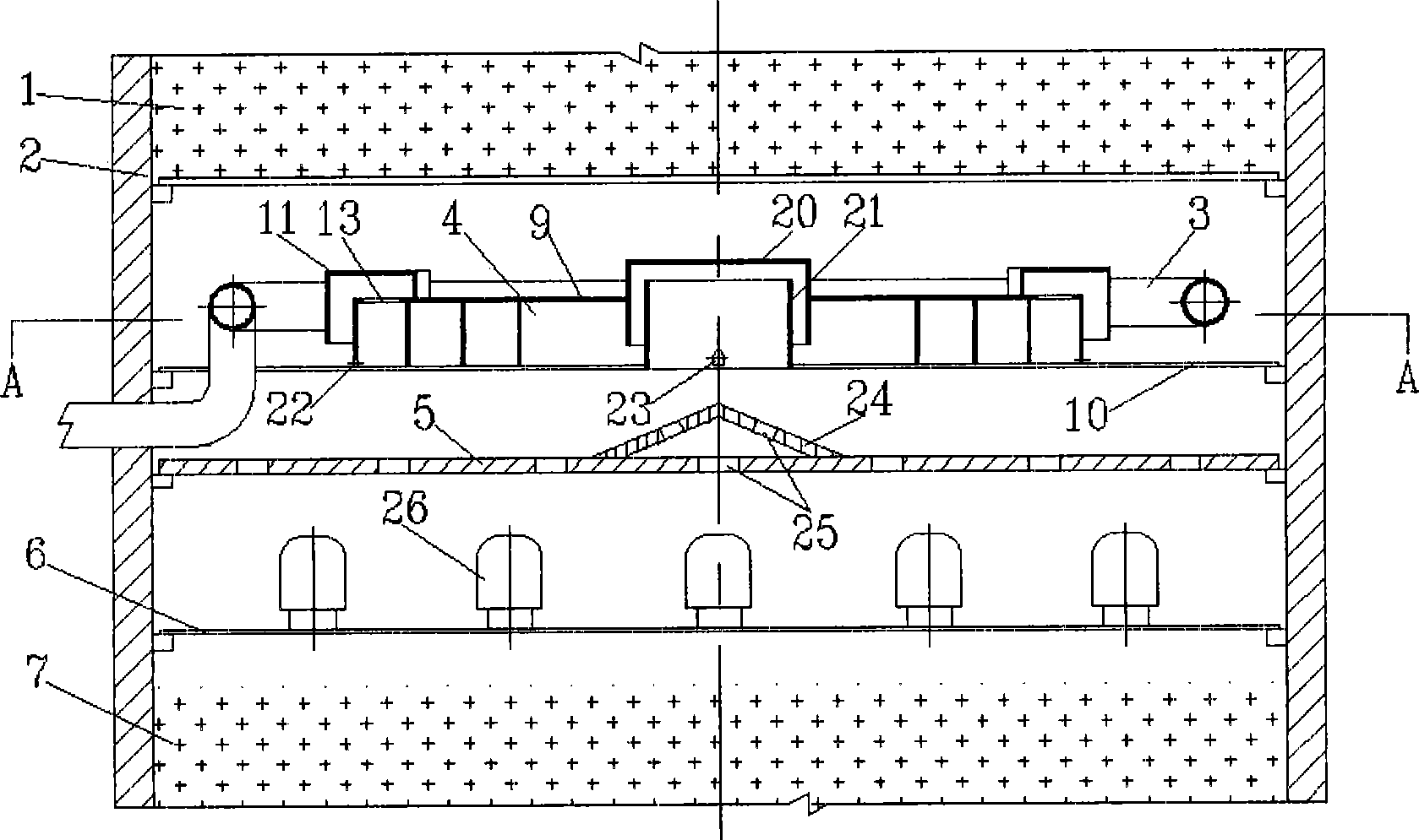
[0056] Adopt the quick cooling box provided by the invention, the structure is as figure 1 As shown, in the cold mold device with a diameter of 1000mm, the desorption efficiency of oxygen in oxygen-enriched water was measured with water and air as the simulated medium. The air and oxygen-enriched water are measured separately and introduced into the quench box for oxygen desorption, and the dissolved oxygen analyzer is used to detect the concentration of dissolved oxygen in the water at the inlet and outlet of the quench box online. 入 、C 出 , the oxygen desorption efficiency is calculated by the following formula:

[0057] Oxygen desorption efficiency:

[0058] C 入 ——Liquid phase oxygen concentration at the inlet of the quenching box, μg / ml

[0059] C 出 ——The liquid phase oxygen concentration at the outlet of the que...

Embodiment 2

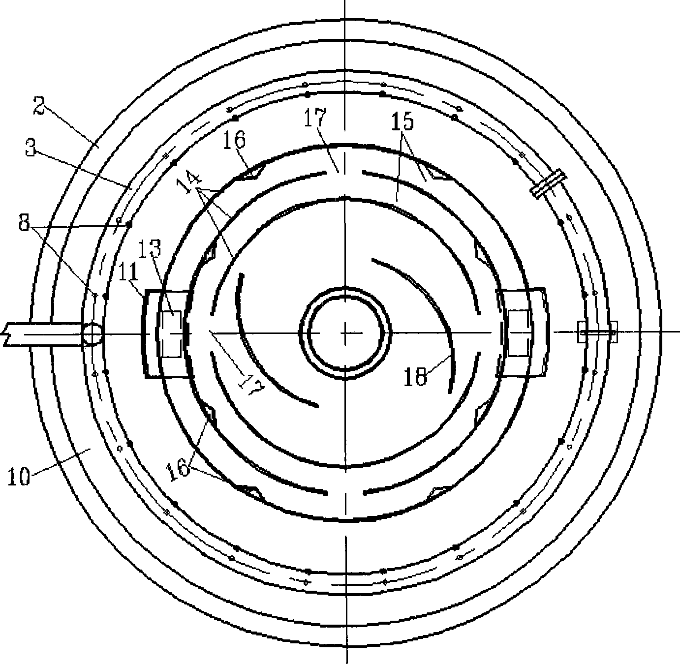
[0068] The allocator structure is like image 3 As shown, the swirl structure is arranged at the nozzle on the central tube. In the cold model test device with a diameter of 500mm, 3 distributors are set on the distribution plate, and the swirl structure of the distributor is composed of 4 swirl sheets. The liquid phase distribution curve is measured with water and air as the simulated medium, and the flow rate is 1.5m 3 / h of water, the flow rate is 180Nm 3 After the two phases of the / h air are mixed and flow into the distributor to distribute the fluid, the liquid phase is sampled and measured under the distributor, and the liquid distribution curve is obtained. The results are shown in Figure 9 Curve B in.

Embodiment 3

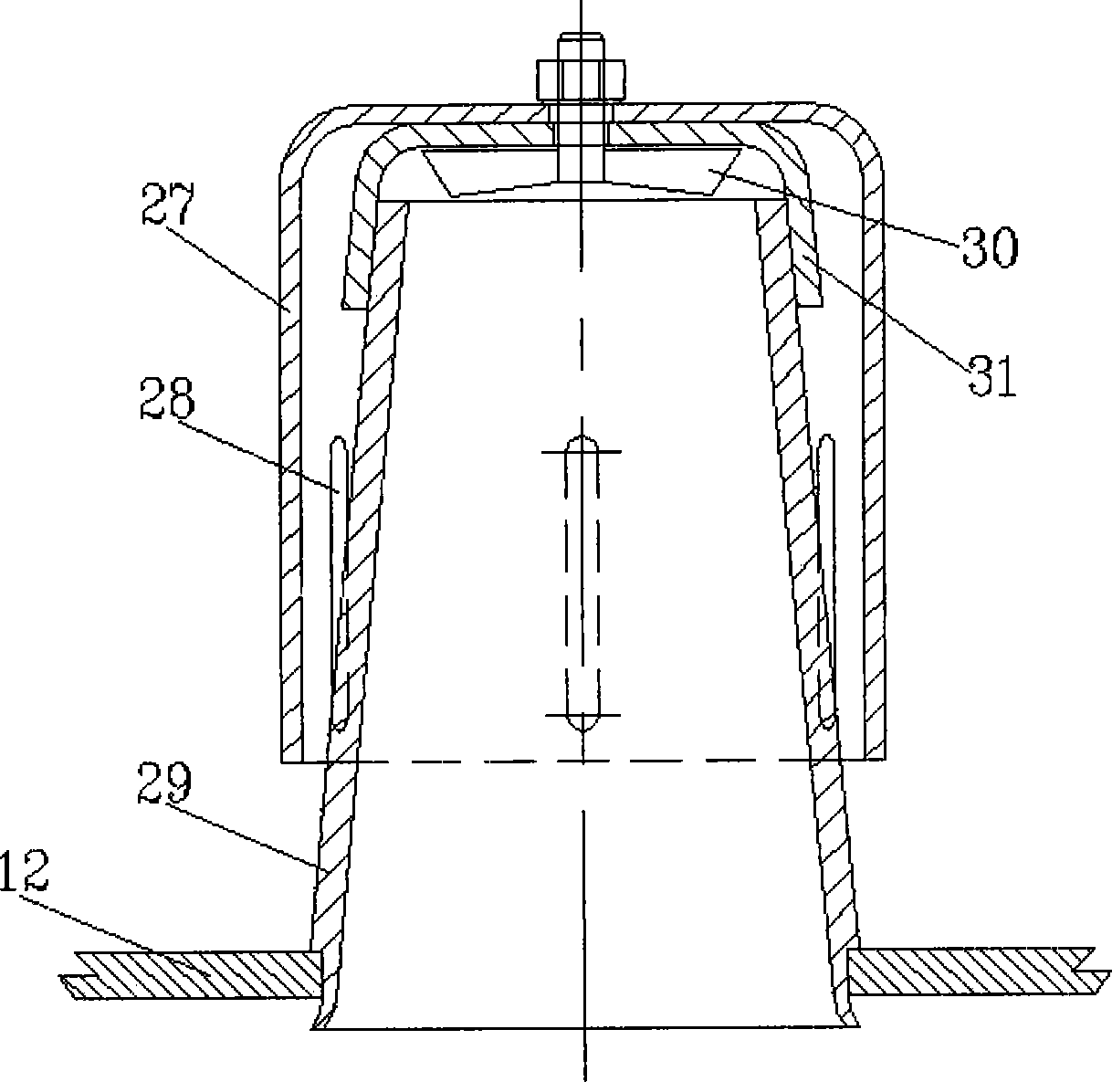
[0070] The allocator structure is like Figure 4 As shown, the swirl structure is arranged at the lower nozzle of the central tube. Test method is with embodiment 2, and liquid phase distribution curve sees Figure 9 Curve C in.


PUM

PropertyMeasurementUnit
porosityaaaaaaaaaa

Abstract

Disclosed is a stream mixing distribution system, and the stream mixing distribution system is composed of a refrigerant pipe (3), a quench box (4), a rectification sieve tray (5) and a distributor disc (6), wherein, the refrigerant pipe (3) is positioned at the upper part of the quench box (4) or positioned in an annular space surrounded by the outer wall of the quench box (4) and the inner wall of a reactor (2), the rectification sieve tray (5) is positioned at the lower part of the quench box (4), the distributor disc (6) is positioned at the lower part of the rectification sieve tray (5), and a plurality of distributors (26) are evenly distributed on the distributor disc (6), and the system is characterized in that each distributor (26) is composed of a bubble cap (27), a center pipe (29), a journal (31) and a rotational flow structure (30), the center pipe (29) is a circular pipe with two open ends, and the bottom part thereof is fixed on the distributor disc, the bubble cap (27) of each distributor is fixed above the center pipe (29) through the journal (31), and the rotational flow structure (30) is fixed at the top part of the center pipe (29) or the outlet of the center pipe (29). The stream mixing distribution system has better mixing distribution effects, and can also save the inner space of the reactor.

Description

technical field [0001] The present invention relates to a flow mixing and distributing device between adjacent beds in a multi-bed downflow reactor, more specifically, to a gas-liquid two-phase reactant flow remixed and distributed downflow in a fixed bed hydrogenation reactor mechanical device. Background technique [0002] In the petrochemical industry, multi-bed downflow catalytic reactors are used in hydrotreating, hydrodesulfurization, hydrofining, hydrocracking and dewaxing processes. During these processes, the gas-liquid mixture flows side by side and passes through the catalyst bed for reaction. At the same time, the hydrogenation reaction is an exothermic process. When the stream passes through the catalyst bed, the temperature will gradually increase. Due to unevenness, channeling or short circuit is formed, and uneven temperature distribution occurs, which will reduce the utilization rate of the catalyst and affect the quality of the product. If the flow distri...

Claims


Application Information

Patent Timeline
Patent Type & Authority Applications(China)
IPC IPC(8): B01J8/04B01F3/04C10G35/04C10G49/00
Inventor 王少兵张占柱杨克勇毛俊义赵志海师峰渠红亮石亚华
Owner CHINA PETROLEUM & CHEM CORP
Why Eureka
Try Eureka