Hydraulic turbine

a technology of hydraulic turbines and turbine blades, applied in the direction of engine seals, machines/engines, engine components, etc., can solve the problems of large loss, large clearance, and now demanding to get a low vibration level

Active Publication Date: 2018-01-25
GE RENEWABLE TECH
View PDF13 Cites 1 Cited by
  • Summary
  • Abstract
  • Description
  • Claims
  • Application Information

AI Technical Summary

Benefits of technology

[0013]It is an object of the present invention to decrease in a simple and effective way the press

Problems solved by technology

For instance, the customer is now demanding to get a low vibration level in the turbine pit because high intensity vibrations can damage the machine.
Reducing this oscillating pressure field (or pressure fluctuation level) in the vane-less gap VG is a continuous challenge for the designers and

Method used


Image

  • Hydraulic turbine
  • Hydraulic turbine
  • Hydraulic turbine

Examples


Embodiment Construction

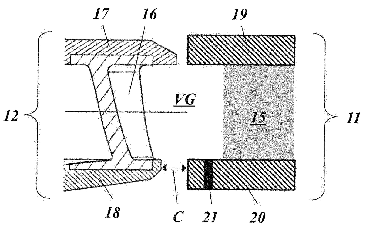
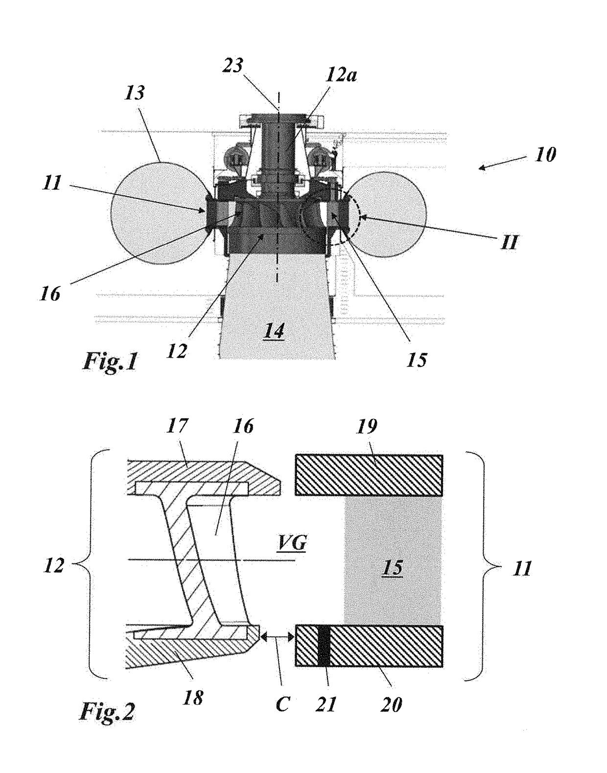
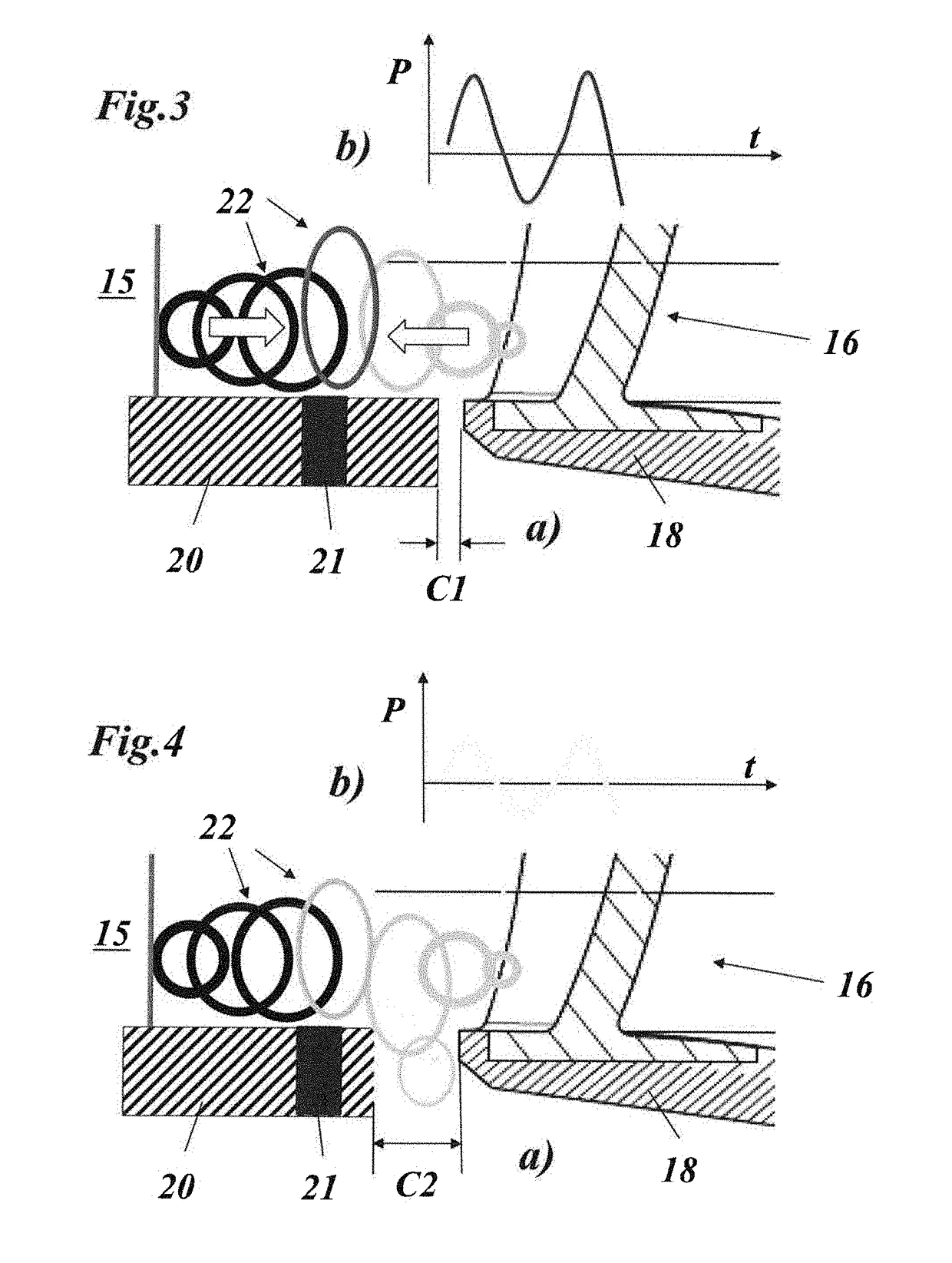
[0036]The known solutions to reduce the pressure fluctuations are essentially focused on the design and the shape of components close to the vane-less gap (VG) area.

[0037]Among the most known and identified methods of reducing pressure fluctuations are: changing the blade number and / or the guide vanes number; changing the runner blade diameter, the inner diameter of the guide vane and / or the pitch diameter; changing the design of the runner at the turbine inlet, for example the shape of the leading edge (parabolic shape or linear), the thickness of the blade and / or the curvature of blades.

[0038]Some of these solutions are identified in the following publication: Zhigang et al. Pressure fluctuations in the vane-less space of high-head-pump-turbines—A review. Renewable and Sustainable Energy Reviews. 41 (2015) 965-974.

[0039]The above ways have counter effects like hydraulic efficiency decrease, hydraulic instabilities increase and thus a trade-off shall be found to reach minimum press...


PUM


Abstract

A hydraulic turbine includes a rotor with a runner, which is concentrically surrounded by a stator, whereby the runner comprises a plurality of runner blades arranged and distributed in a ring around a rotor axis, and each runner blade extends between a runner crown and a runner band; whereby the stator comprises a plurality of guide vanes arranged and distributed in a ring around the rotor axis, and each guide vane extends between an upper stator ring and a lower stator ring; and whereby a predetermined clearance is provided at least between the runner band and the lower stator ring. A substantial reduction of pressure pulsations in the vane-less gap between said runner blades of said runner is achieved by substantially increasing said predetermined clearance.

Description

BACKGROUND OF THE INVENTION[0001]The present invention relates to the technology of hydraulic machines. It refers to a hydraulic turbine.[0002]When designing a hydraulic turbine multiple objectives need to be reached simultaneously. Efficiency appears as the predominant one. However, extending the operating range and ensuring a good behaviour of the machine in terms of stability and safety become more and more important. For instance, the customer is now demanding to get a low vibration level in the turbine pit because high intensity vibrations can damage the machine.[0003]These vibrations result from the mechanical response of the structure to hydraulic excitations coming from the interactions between the rotor (the runner) and stator (RSI).[0004]FIG. 1 shows as an example the main parts of a hydraulic turbine of the Francis type. The hydraulic turbine 10 of FIG. 1 comprises a vertical rotor with a runner 12 and a turbine shaft 12a. Runner 12 comprises a plurality of runner blades ...

Claims


Application Information

Patent Timeline
IPC IPC(8): F03B3/18F03B11/04F03B3/02F03B11/00
CPCF03B3/18F03B11/006F16J15/164F03B3/02F03B11/04F03B3/12F03B3/125F05B2260/96Y02E10/20
Inventor MARTINEZ, LIONELHOUDELINE, JEAN-BERNARDDARONA, GEOFFREYBERAL, CLAUDE
Owner GE RENEWABLE TECH
Why Eureka
Try Eureka