Fluid rotary union

a technology of rotary union and fluid, which is applied in the direction of adjustment joints, pipe joints, pipe/joints/fittings, etc., can solve the problems of affecting the design of the fru to transport several fluids at a time, the difficulty of reducing the design complexity of the fru, and the risk of man-made fluids

Active Publication Date: 2005-03-03
FOCAL TECH
View PDF24 Cites 29 Cited by
  • Summary
  • Abstract
  • Description
  • Claims
  • Application Information

AI Technical Summary

Problems solved by technology

Additionally, the fluids may be hazardous to man, to his environment or to the equipment used to transport the fluids.
Designing an FRU to transport several fluids at a time is generally more difficult than designing an FRU that only carries one fluid at a time.
In particular, when fluids are not identical, e.g., the fluids are at different pressures and / or temperatures, the design of an FRU is relatively complex.
Each of the FRUs found in the foregoing patents or patent applications are generally designed for specific applications and may exhibit sealing problems, especially when utilized to transport fluids at high temperatures and / or pressures or when the fluids are corrosive or hazardous fluids.
Further, due to the designs of these prior art FRUs, the FRUs are often difficult to repair or reconfigure.
While the above-disclosed FRUs are functional, the above-disclosed FRUs can be relatively expensive to manufacture and difficult to repair.

Method used


Image

  • Fluid rotary union
  • Fluid rotary union
  • Fluid rotary union

Examples


Embodiment Construction

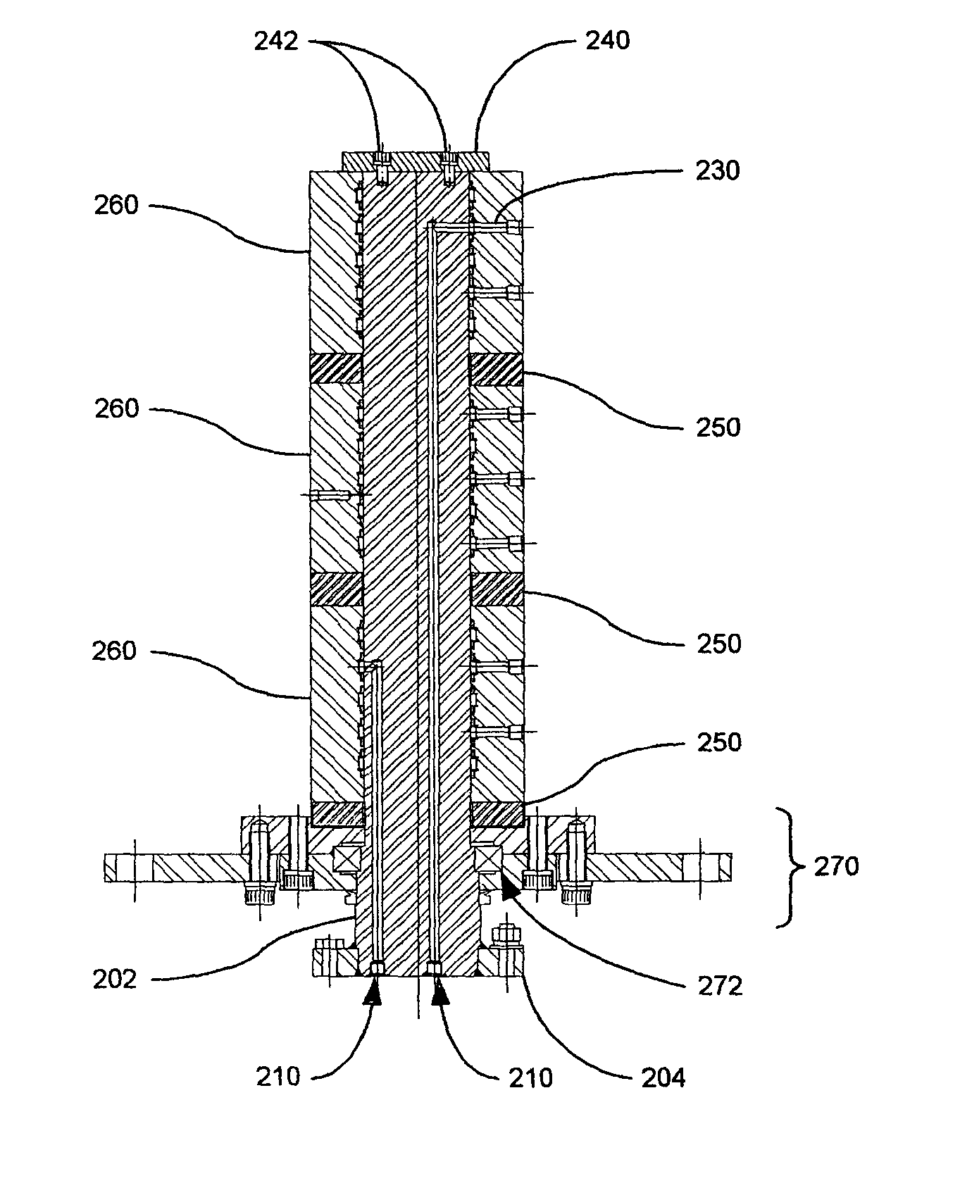
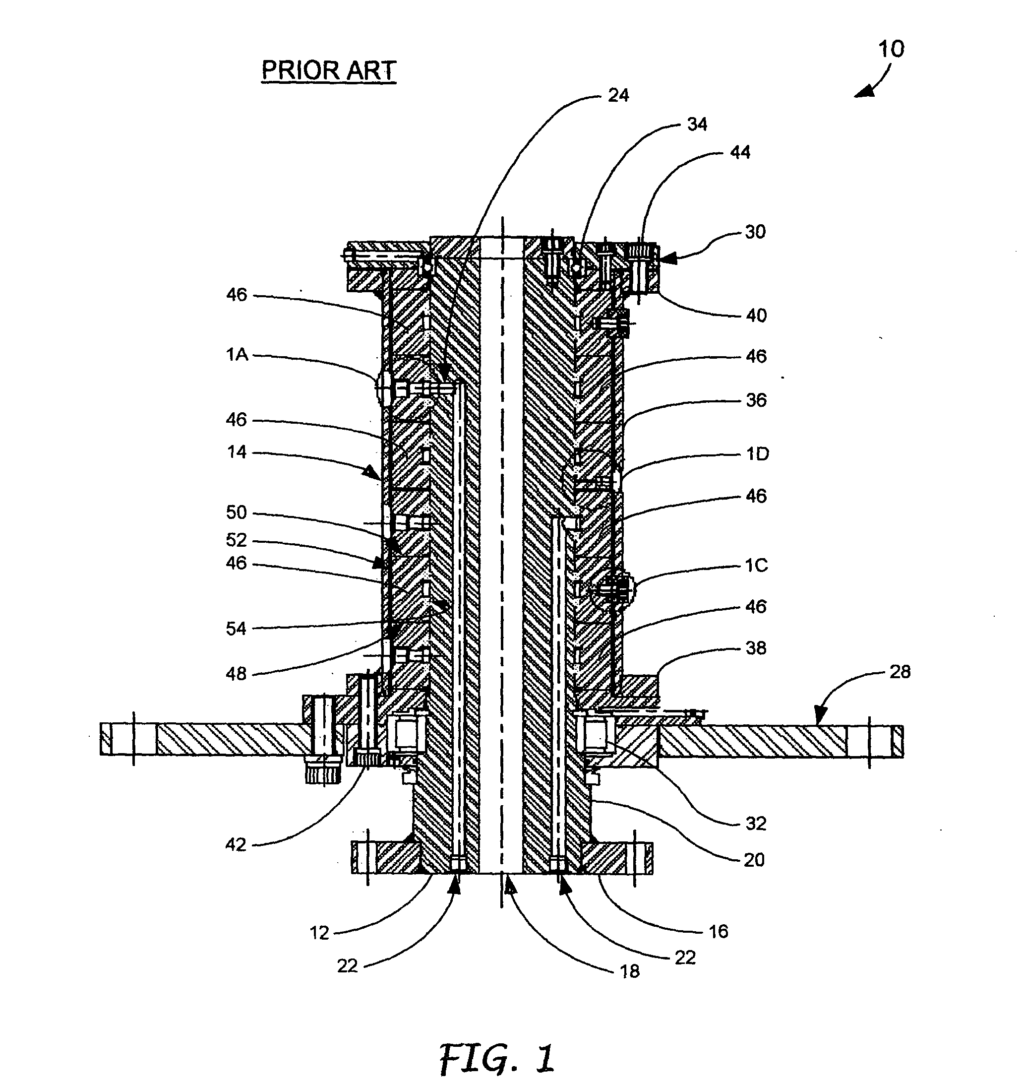
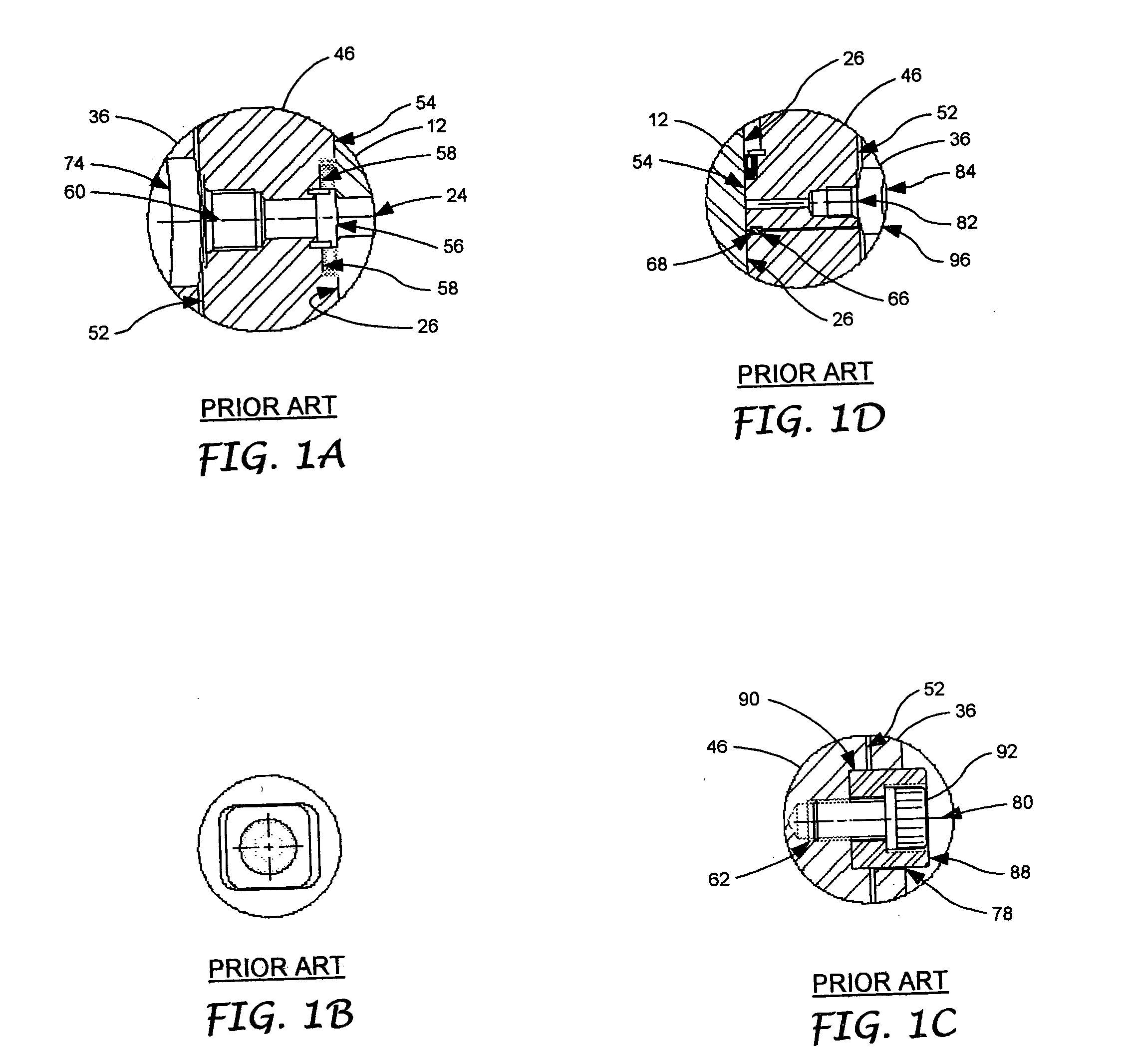
[0025] The present invention generally overcomes many of the problems associated with the prior art by providing a fluid rotary union (FRU) for use in a fluid delivery system that is capable of transporting multiple fluids with little or no loss of pressure or sealing problems in an economical manner. The FRU can be modified to accommodate different numbers of flow channels and is designed to ensure efficient rotation between incoming and outgoing conduit arrangements. The FRU uses a semi-independent floating design that includes a plurality of individual segments, each of which is effectively coupled to an adjacent segment or segments and / or a housing (i.e., when the segment is an end segment) using a coupler, i.e., a torque transmitting / misalignment device. Each segment contains one or more fluid channels and is capable of “floating” with a central shaft that includes a plurality of longitudinally extending bores, each of which is capable of carrying fluid. The bores terminate at ...


PUM


Abstract

A fluid rotary union (FRU) includes a first member and a second member. The first member includes a plurality of spaced longitudinally directed bores of different lengths, each of which terminate at an associated radially directed bore communicating the longitudinally directed bores with an outer surface of the first member. The second member includes a first housing, a plurality of longitudinally adjacent segments and a plurality of couplers positioned between adjacent ones of the segments and the first housing and an adjacent one of the segments. Each of the segments has at least one circumferential groove formed into an inner surface for providing fluid communication with one of the associated radially directed bores of the first member. A radially directed bore extends from each of the grooves in the segment to the outer surface of the segment.

Description

BACKGROUND OF THE INVENTION [0001] The present invention is generally directed to a fluid rotary union (FRU) and, more specifically, an FRU that is designed to operate in a relatively effective manner. [0002] There are numerous instances in which fluids are transported from one location to another. The fluids may be gases or liquids and may be at various temperatures and pressures. Additionally, the fluids may be hazardous to man, to his environment or to the equipment used to transport the fluids. Often, especially in the oil and gas industry, it is necessary to transport a fluid from an offshore location, as at a mooring supporting a riser from a subsea wellhead, to a ship (tanker) for transfer to shore. As a ship weathervans about its mooring, it is desirable to accommodate relative rotational movement between elements in a fluid flow path, i.e., that the equipment be able to accommodate changes in orientation between adjacent conduits to minimize or prevent loss of fluid at the ...

Claims


Application Information

Patent Timeline
Patent Type & Authority Applications(United States)
IPC IPC(8): F16L27/087F16L39/04
CPCF16L39/06F16L27/087
Inventor FALCONER, DARCY RAYMOND
Owner FOCAL TECH
Why Eureka
Try Eureka