

Developer carrying member and developing method by using thereof
Inactive Publication Date: 2005-03-03
CANON KK
View PDF19 Cites 10 Cited by
- Summary
- Abstract
- Description
- Claims
- Application Information
AI Technical Summary
Benefits of technology
Further, the purpose of the present invention is to provide a developer carrying member which can control uneven charge on the toner as well as appropriate and rapid electrification to the toner by means of reduction of toner attachment onto the surface of the developer carrying member and of toner melt-adhesion which appear when the image is formed using the toner with small particles size and high degree of sphericity, and a developing method which uses the above developer carrying member.
Further, the purpose of the present invention is to provide a developer carrying member which does not cause deterioration easily of resin-coated layer on th
Problems solved by technology
Particularly, the charge-up phenomenon is likely to occur particularly under low humidity where the charge amount of the toner coated on the developing sleeve becomes excessively high owing to the contact with the developing sleeve during repeated rotation of the developing sleeve, resulting in immobilization of the toner on the developing sleeve by drawing between the toner and the reflection force on the developing sleeve failing in transfer of the toner from the developing sleeve to the electrostatic latent image on the photosensitive drum that is charge-up phenomenon.
When the charge-up phenomenon occurs, it becomes difficult for the toner in the upper layer to charge resulting in reduction of developing amount of the toner.
Consequently, there sometimes occur problems such as thinning of the line image and lowering of image density of the solid image.
Further, the toner which has failed in appropriate charging owing-to the charge-up phenomenon may flow on the developing sleeve off the control to make spotty or wavy unevenness that is the blotching phenomenon.
Furthermore, the tendency is decrease of a fixation temperature for the purpose of time reduction for fast copying and saving electric power.
In such situations, the toner, particularly under a low temperature and low humidity is more likely to attach electrostatistically on the developing sleeve because of increased charge per unit weight, while under high temperature and high humidity, blotching and melt-adhesion by the toner are likely to occur on the developing sleeve.
In this developing sleeve, however, when adding much amount of electroconductive fine powder, appropriate electrification to the toner is decreased leading to difficulty of obtaining high image density particularly in the environment of high temperature and high humidity, though the case is good for charge-up and sleeve ghost.
Further, when adding much amount of electroconductive fine powder, the resin-coated layer becomes friable being easy to be scraped as well as configuration of the surface is likely to be uneven, and when advancing endurance for a large number of sheets, surface roughness and surface composition of the resin-coated layer is altered resulting in frequent occurrence of poor conveyance of the toner and inhomogeneous electrification to the toner.
However,
Method used
View moreImage
Smart ImageViewing Examples

Examples
 PUM
| Property | Measurement | Unit |
|---|---|---|
| Fraction | aaaaa | aaaaa |
| Fraction | aaaaa | aaaaa |
| Length | aaaaa | aaaaa |
Abstract
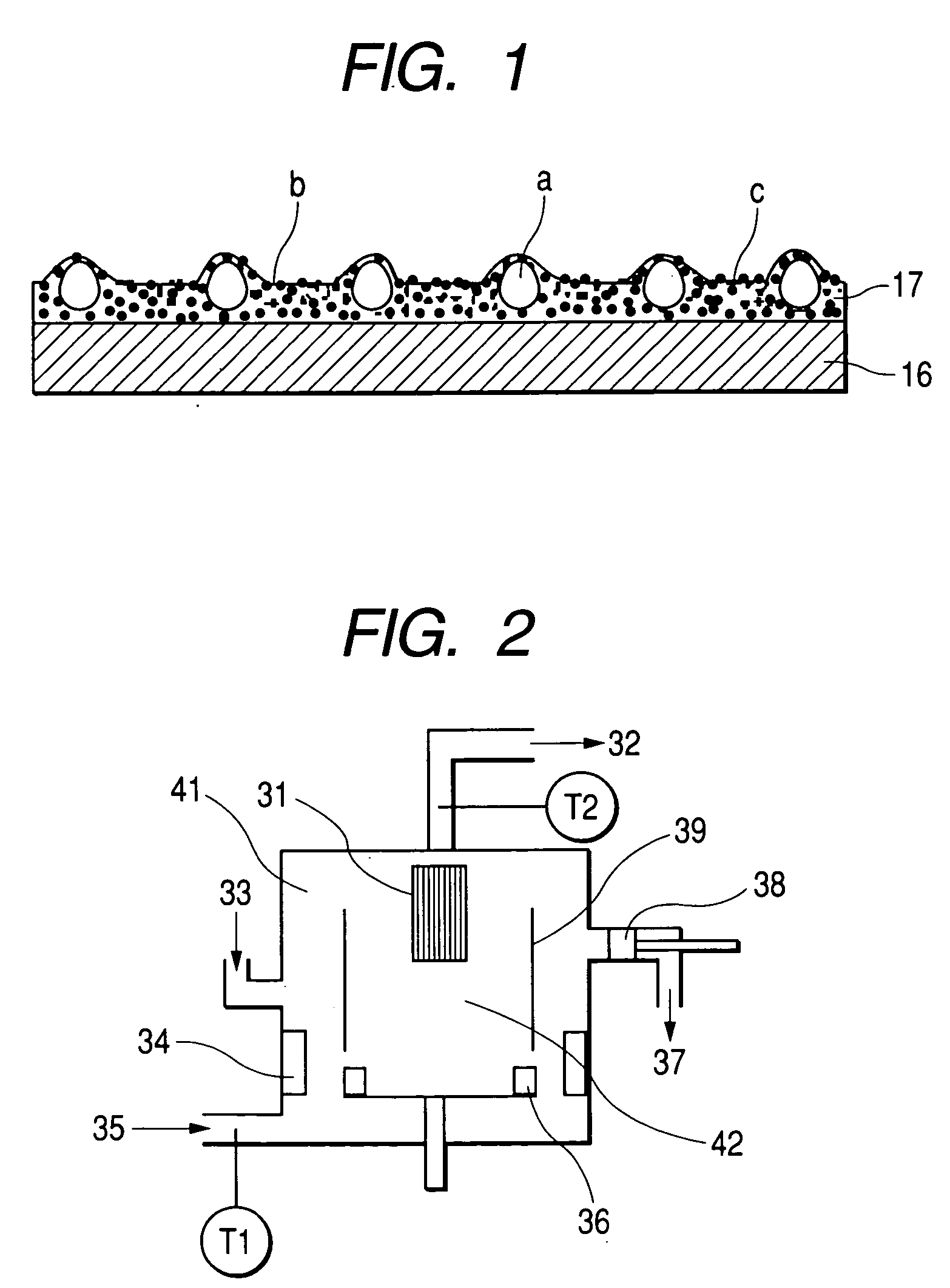
The present invention relates to a developer carrying member for carrying a developer having at least a substrate and a resin-coated layer formed on the surface of the substrate. The developer carrying member is the one which carries a one-component developer to visualize the electrostatic latent image carried by the electrostatic latent image carrying member, the resin-coated layer contains at least a binder resin, graphitized particles and roughing particles, the graphitized particles has 0.20 to 0.95 of graphitization degree (p (002)), and wherein in the surface configuration of the resin-coated layer as measured by use of focusing optical laser, the volume (B) of a microtopographical region defined by a certain area (A) of the microtopographical region without convexity formed by the roughing particles meets the following relationship 4.5≦B/A≦6.5, and the resin-coated layer has 0.9 to 2.5 μm of arithmetic mean roughness (Ra).
Description
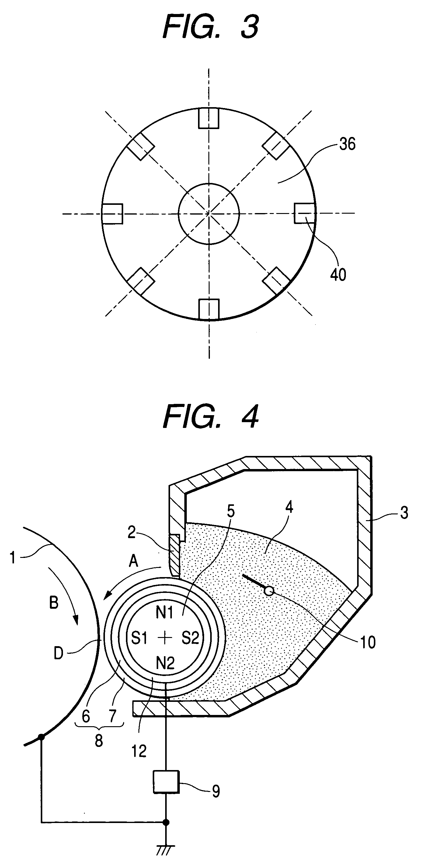
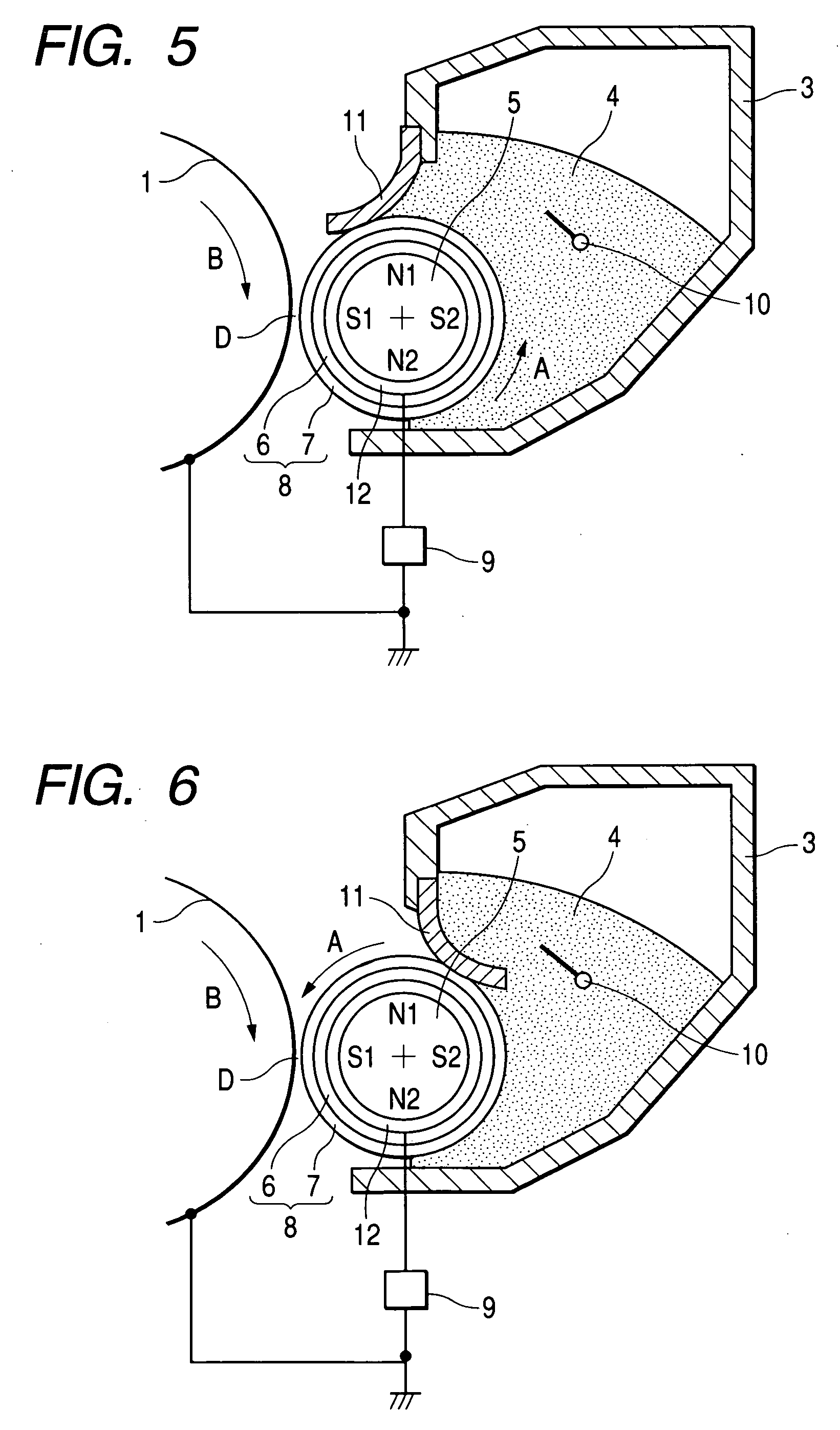
BACKGROUND OF THE INVENTION 1. Field of the Invention The present invention relates to a developer carrying member used in a developing apparatus to form a toner image by developing an electrostatic latent image formed on the image carrying member such as an electrophotographic photosensitive member or electrostatic recording dielectric. The invention also relates to a developing method using the above described developer carrying member. 2. Related Background Art Electrophotography conventionally forms an electrostatic latent image on the support thereof (photosensitive drum) by various measures using a photoconductive material, then develops the electrostatic latent image by a developer (toner) to form the toner image and transfer the toner image on a transfer material, such as paper, if appropriate, followed by fixation of the toner image on the transfer material by application of heat, pressure or both heat and pressure to obtain the print or copy. Developing systems in the ...
Claims
Login to View More Application Information
Patent Timeline
 IPC IPC(8): G03G9/10G03G15/08G03G15/09
CPCG03G15/0813G03G15/0818G03G15/0928G03G2215/0634Y10T428/254Y10T428/2991Y10T428/24893Y10T428/252Y10T428/24372Y10T428/24802Y10T428/25
InventorSHIMAMURA, MASAYOSHIFUJISHIMA, KENJIOKAMOTO, NAOKIAKASHI, YASUTAKAOTAKE, SATOSHISAIKI, KAZUNORIGOSEKI, YASUHIDE
OwnerCANON KK