Methods and apparatus for operating gas turbine engines

a gas turbine engine and gas turbine technology, applied in the field can solve the problems of accumulating ice on exposed external engine structures, affecting the operation of gas turbine engines, so as to facilitate ice accumulation and prevent ice accumulation

Active Publication Date: 2005-03-10
GENERAL ELECTRIC CO
View PDF30 Cites 87 Cited by
  • Summary
  • Abstract
  • Description
  • Claims
  • Application Information

AI Technical Summary

Benefits of technology

[0005] In one aspect, a method for assembling a turbine engine to facilitate preventing ice accumulation on the turbine engine during engine operation is provided. The method comprises coupling at least one heat pipe to the engine such that a first end of the at least one heat pipe is coupled in thermal communication with a heat source, and coupling a second end of the at least one heat pipe in thermal communication with an outer surface of an engine component that is upstream from the heat source.

Problems solved by technology

When engines operate in icing conditions, i.e., exposed to clouds of super-cooled water droplets, ice may accumulate on exposed external engine structures.
More specifically, if engines are operated within icing conditions at low power for extended periods of time, ice accumulation within the engine and over exposed engine structures may be significant.
Over time, continued operation of the engine, or a throttle burst from lower power operations to higher power operations, or vibrations due to either turbulence or asymmetry of ice accretion, may cause the accumulated ice build-up to be ingested by the high pressure compressor.
This sudden increase in aft stage corrected core speed may adversely impact compressor stall margin.
In extreme cases, it may also lead to an engine flame out.
However, the increased operating temperature and the bleed systems may decrease engine performance.
In addition to the increased cost, such valving may pose a reliability problem.
However, during flight and over time, the effectiveness of the deicing solution may decrease.
More specifically, during engine operation, evaporative cooling may still cause freezing and ice accumulation over external engine surfaces, such as a front frame of the engine.
Conventional electrical heating is an option, but it requires large quantities of electricity for performing the de-icing operation and may require additional electrical generators, electrical circuits and complex interaction logic with the airplane's computers with the attendant increased cost, weight and performance penalties.

Method used


Image

  • Methods and apparatus for operating gas turbine engines
  • Methods and apparatus for operating gas turbine engines
  • Methods and apparatus for operating gas turbine engines

Examples


Embodiment Construction

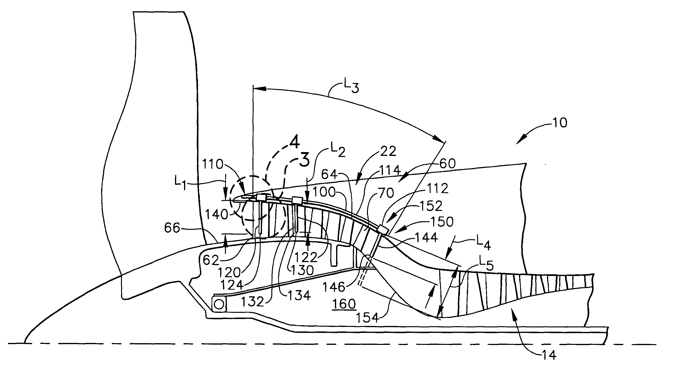
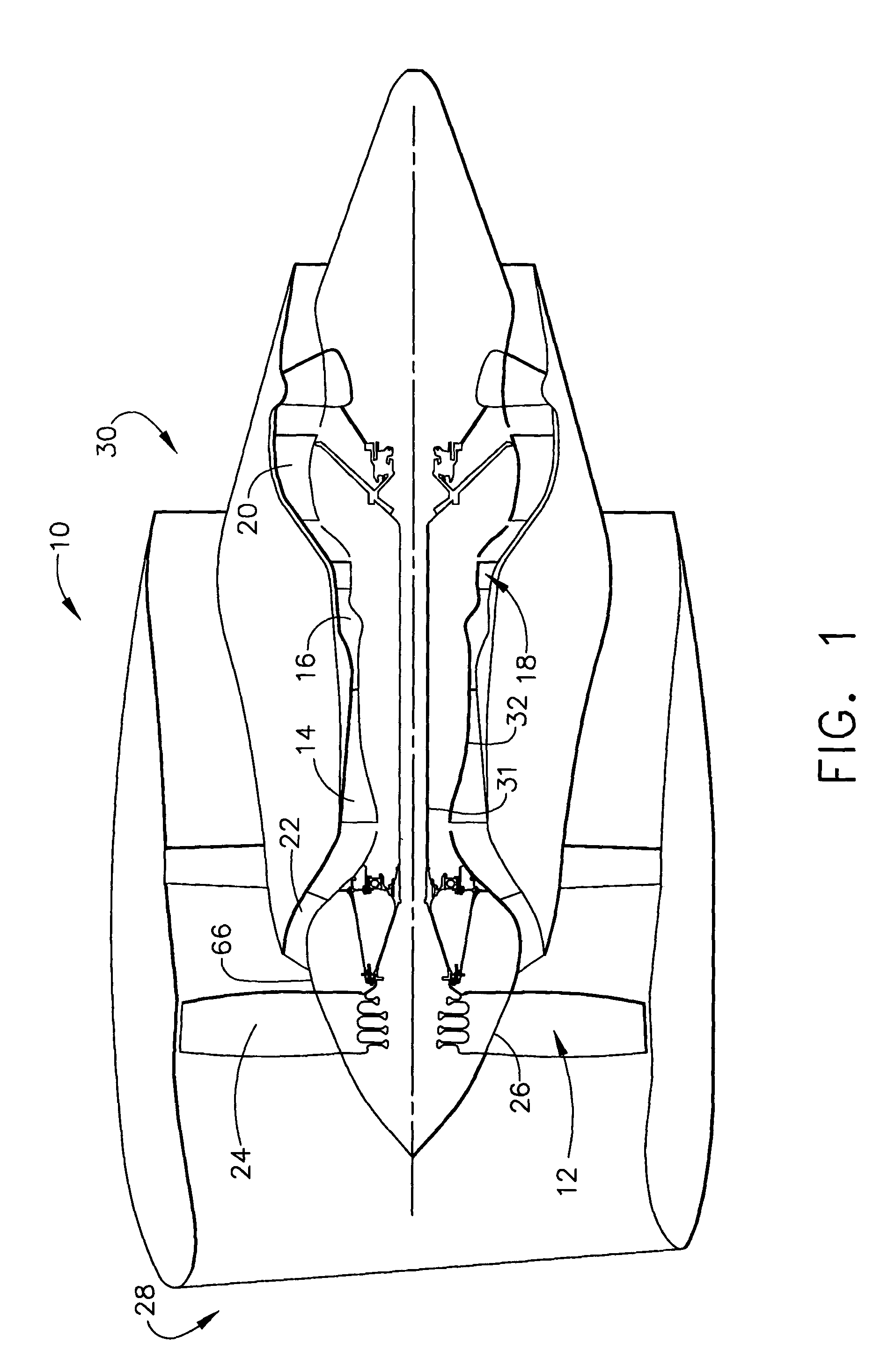
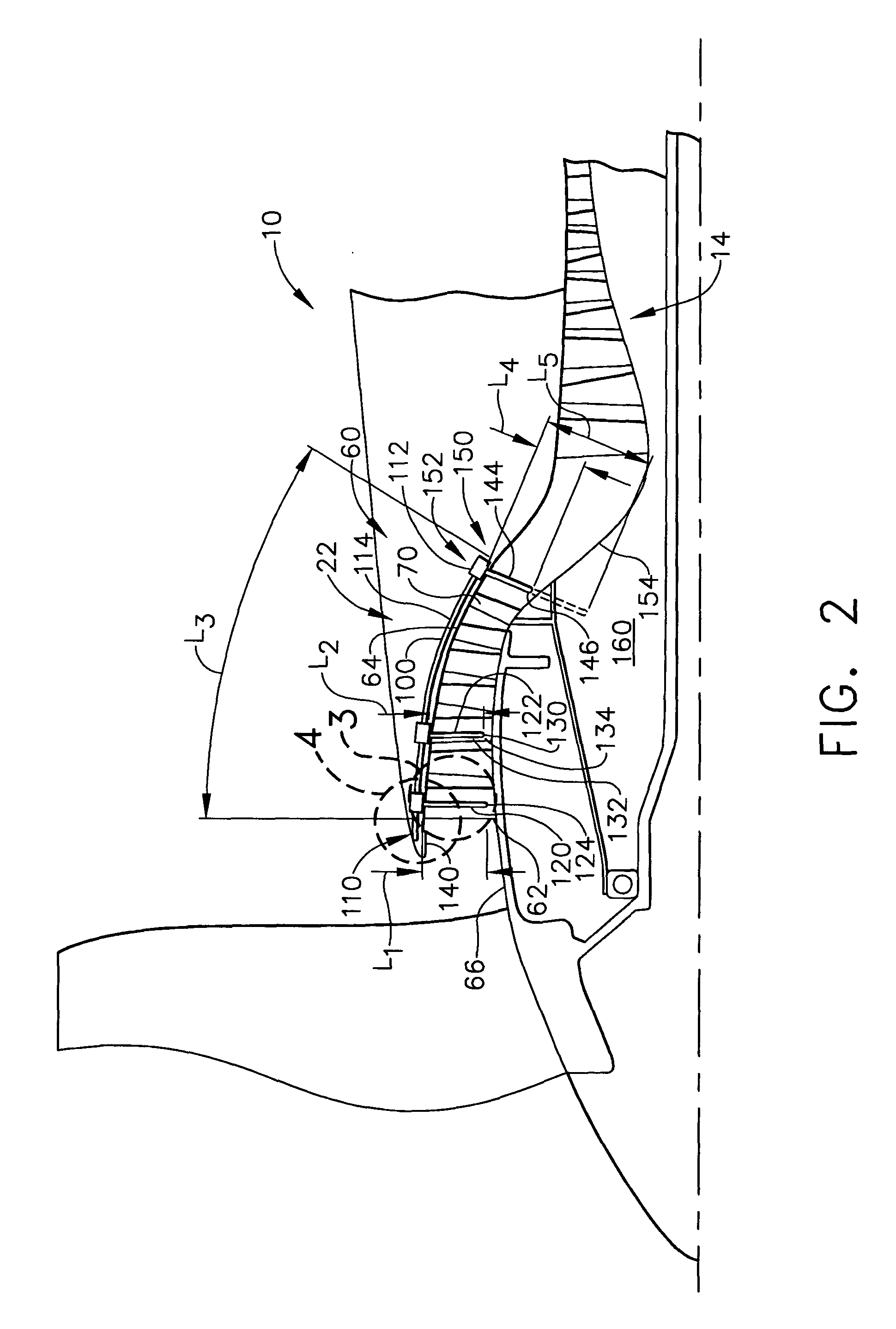
[0013]FIG. 1 is a schematic illustration of a gas turbine engine 10 including a fan assembly 12, a high pressure compressor 14, and a combustor 16. Engine 10 also includes a high pressure turbine 18, a low pressure turbine 20, and a booster 22. Fan assembly 12 includes an array of fan blades 24 extending radially outward from a rotor disc 26. Engine 10 has an intake side 28 and an exhaust side 30. In one embodiment, the gas turbine engine is a GE90 available from General Electric Company, Cincinnati, Ohio. In an alternative embodiment, engine 10 includes a low pressure compressor. Fan assembly 12, booster 22, and turbine 20 are coupled by a first rotor shaft 31, and compressor 14 and turbine 18 are coupled by a second rotor shaft 32.

[0014] In operation, air flows through fan assembly 12 and compressed air is supplied to high pressure compressor 14 through booster 22. The highly compressed air is delivered to combustor 16. Hot products of combustion (not shown in FIG. 1) from combus...


PUM


Abstract

A method facilitates assembling a turbine engine to facilitate preventing ice accumulation on the turbine engine during engine operation. The method comprises coupling at least one heat pipe to the engine such that a first end of the at least one heat pipe is coupled in thermal communication with a heat source, and coupling a second end of the at least one heat pipe in thermal communication with an outer surface of an engine component that is upstream from the heat source.

Description

BACKGROUND OF THE INVENTION [0001] This invention relates generally to gas turbine engines, and more particularly, to methods and apparatus for operating gas turbine engines. [0002] Gas turbine engines typically include low and high pressure compressors, a combustor, and at least one turbine. The compressors compress air which is channeled to the combustor where it is mixed with fuel. The mixture is then ignited for generating hot combustion gases, and the combustion gases are channeled to the turbine(s) which extracts energy from the combustion gases for powering the compressor(s), as well as producing useful work to propel an aircraft in flight or to power a load, such as an electrical generator. [0003] When engines operate in icing conditions, i.e., exposed to clouds of super-cooled water droplets, ice may accumulate on exposed external engine structures. More specifically, if engines are operated within icing conditions at low power for extended periods of time, ice accumulation...

Claims


Application Information

Patent Timeline
Patent Type & Authority Applications(United States)
IPC IPC(8): F02C7/047
CPCF02C7/047F05D2260/208Y02T50/675Y02T50/672Y02T50/60F04D29/582F28D15/0275
Inventor VENKATARAMANI, KATTALAICHERI SRINIVASANBUTLER, LAWRENCELEE, CHING-PANG
Owner GENERAL ELECTRIC CO
Why Eureka
Try Eureka