Methods and apparatus for gas turbine engines

a gas turbine engine and gas turbine technology, applied in the direction of machines/engines, climate sustainability, sustainable transportation, etc., can solve the problems of high engine vibration, ice accumulation on exposed engine structures, and ice accumulation over exposed engine structures, so as to facilitate ice accumulation, facilitate ice accumulation, and facilitate ice accumulation

Active Publication Date: 2007-03-22
GENERAL ELECTRIC CO
View PDF13 Cites 4 Cited by
  • Summary
  • Abstract
  • Description
  • Claims
  • Application Information

AI Technical Summary

Benefits of technology

[0005] In one aspect, a method for assembling a turbine engine is provided. The method includes coupling a plurality of fan blades to a fan rotor, and applying a polyurethane material to at least a portion of at least one of the fan blades to facilitate preventing ice accumulation on the at least one fan blade.
[0006] In another aspect, a fan assembly for a gas turbine engine is provided. The fan assembly includes a fan rotor disk, a plurality of fan blades coupled to the fan rotor disk, and a polyurethane material applied to at least a portion of at least one of the fan blades to facilitate preventing ice accumulation on the at least one the fan blade.
[0007] In a further aspect, a gas turbine engine assembly is provided. The gas turbine engine assembly includes a core gas turbine engine, and a fan assembly coupled to the core gas turbine engine. The fan assembly includes a fan rotor disk, a plurality of fan blades coupled to the fan rotor disk, the plurality of fan blades fabricated at least partially from a titanium material, and a polyurethane material applied to at least a portion of at least one of the fan blades to facilitate preventing ice accumulation on the at least one the fan blade.

Problems solved by technology

When engines operate in icing conditions, i.e., exposed to clouds of super-cooled water droplets, ice may accumulate on exposed engine structures.
More specifically, if engines are operated within icing conditions at low power for extended periods of time, ice accumulation within the engine and over exposed engine structures may be significant.
Over this time, large quantities of ice can accrete and may cause high engine vibrations until the ice is shed.
This sudden increase in aft stage corrected core speed may adversely impact compressor stall margin.
In some cases, it may also lead to compressor stall.
However, the increased operating temperature and the bleed systems may decrease engine performance.
In addition to the increased cost, such valving may pose a reliability problem.
However, during flight, de-icing solutions are not applied.
More specifically, during flight, evaporative cooling may still cause freezing and ice accumulation over external engine surfaces, such as a front frame of the engine.
Conventional electrical heating is an option, but it requires electricity for performing the de-icing operation and may require relatively large generators at low speed conditions, electrical circuits, and complex interactive logic with the airplane's computers with the attendant increased cost, weight and performance penalties.

Method used


Image

  • Methods and apparatus for gas turbine engines
  • Methods and apparatus for gas turbine engines
  • Methods and apparatus for gas turbine engines

Examples


Embodiment Construction

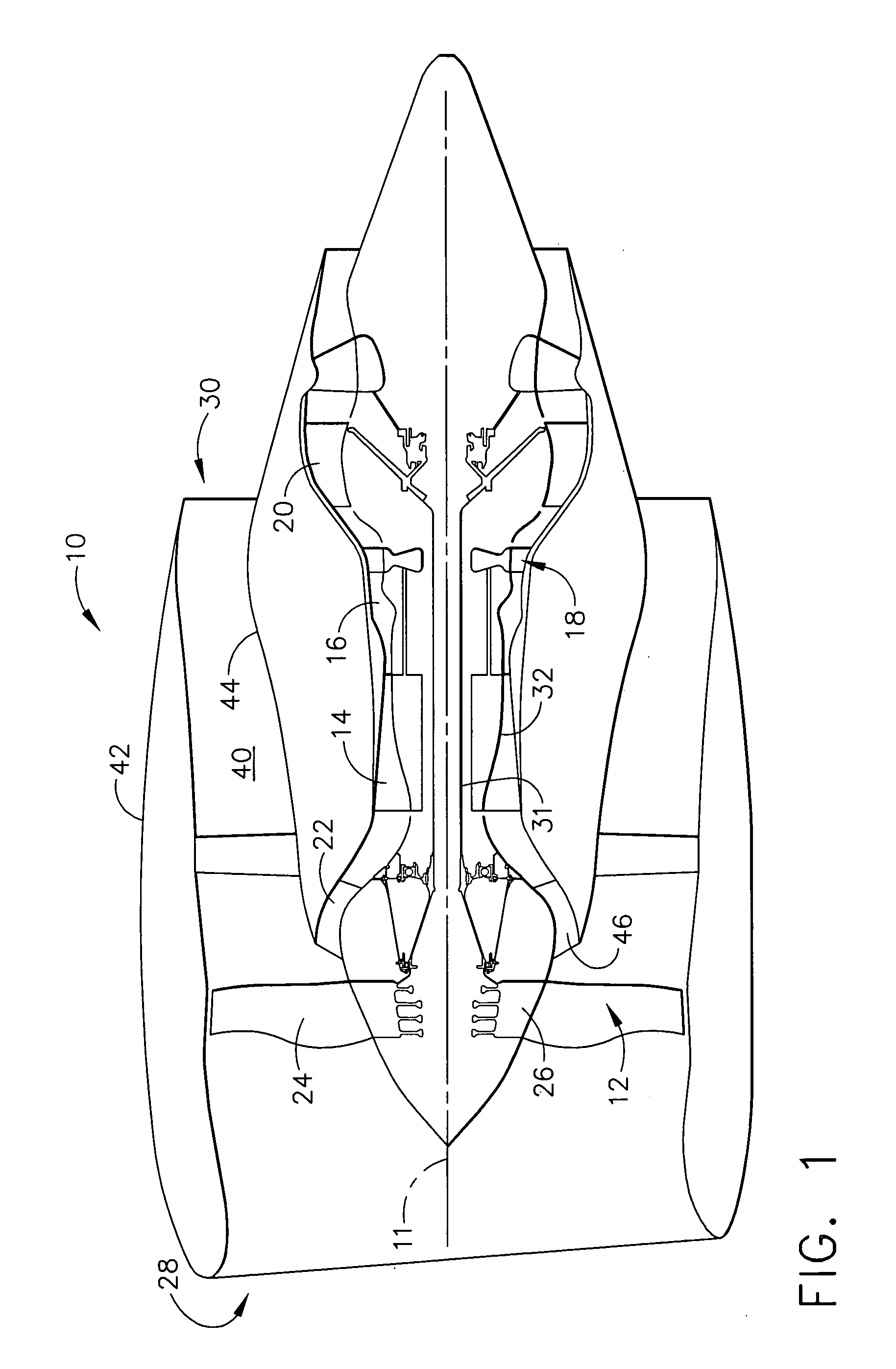
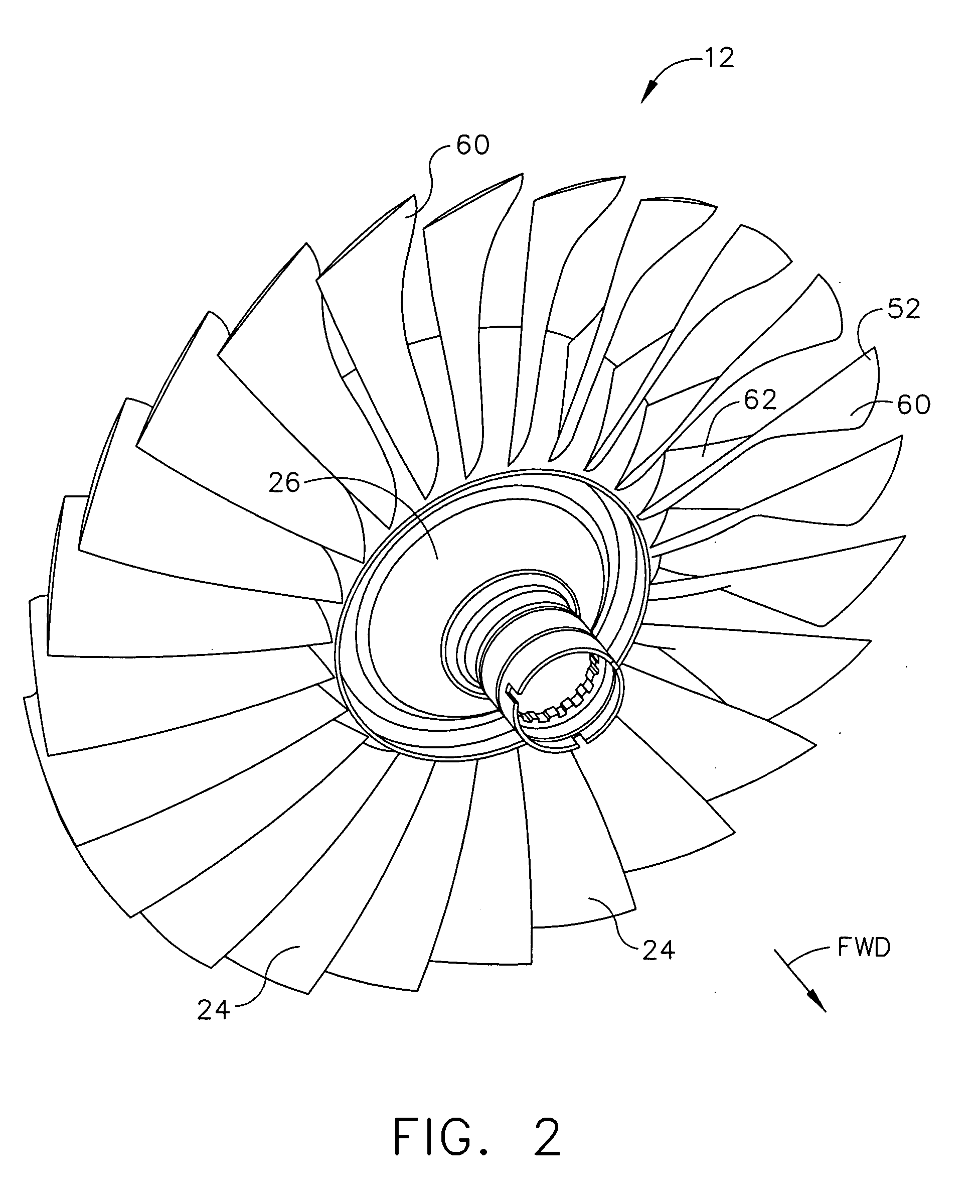
[0013]FIG. 1 is a schematic illustration of an exemplary gas turbine engine assembly 10 having a longitudinal axis 11. Gas turbine engine assembly 10 includes a fan assembly 12, a high pressure compressor 14, and a combustor 16. Engine 10 also includes a high pressure turbine 18, a low pressure turbine 20, and a booster 22. Fan assembly 12 includes an array of fan blades 24 extending radially outward from a rotor disk 26. Engine 10 has an intake side 28 and an exhaust side 30. In the exemplary embodiment, the gas turbine engine is a GE90 available from General Electric Company, Cincinnati, Ohio. Fan assembly 12, booster 22, and turbine 20 are coupled together by a first rotor shaft 31, and compressor 14 and turbine 18 are coupled together by a second rotor shaft 32.

[0014] In operation, air flows through fan assembly 12 and compressed air is supplied to high pressure compressor 14 through booster 22. The booster discharge air is further compressed and delivered to combustor 16. Hot ...


PUM


Abstract

A method for assembling a turbine engine to facilitate preventing ice accumulation on the turbine engine during engine operation, the gas turbine engine including a fan assembly. The method includes coupling a plurality of fan blades to a fan rotor, and applying a polyurethane material to at least a portion of at least one of the fan blades to facilitate preventing ice accumulation on the at least one fan blade.

Description

BACKGROUND OF THE INVENTION [0001] This invention relates generally to gas turbine engines, and more particularly, to methods and apparatus for operating gas turbine engines. [0002] Gas turbine engines typically include an inlet, a fan, low and high pressure compressors, a combustor, and at least one turbine. The compressors compress air which is channeled to the combustor where it is mixed with fuel. The mixture is then ignited for generating hot combustion gases. The combustion gases are channeled to the turbine(s) which extracts energy from the combustion gases for powering the compressor(s), as well as producing useful work to propel an aircraft in flight or to power a load, such as an electrical generator. [0003] When engines operate in icing conditions, i.e., exposed to clouds of super-cooled water droplets, ice may accumulate on exposed engine structures. More specifically, if engines are operated within icing conditions at low power for extended periods of time, ice accumula...

Claims


Application Information

Patent Timeline
Patent Type & Authority Applications(United States)
IPC IPC(8): F01D5/14
CPCF01D5/14Y02T50/672F01D25/02Y02T50/60
Inventor SCHILLING, JAN CHRISTOPHER
Owner GENERAL ELECTRIC CO
Why Eureka
Try Eureka