Ice protection system for an aircraft engine

a technology for aircraft engines and ice protection systems, which is applied in the direction of hot gas positive displacement engine plants, engine components, machines/engines, etc., can solve the problems of ice accumulation on exposed external engine structures, ice accumulation over exposed engine structures, and ice accumulation to be ingested by high-pressure compressors, so as to facilitate ice accumulation and facilitate ice formation , the effect of preventing ice accumulation

Inactive Publication Date: 2005-02-24
GENERAL ELECTRIC CO
View PDF17 Cites 7 Cited by
  • Summary
  • Abstract
  • Description
  • Claims
  • Application Information

AI Technical Summary

Benefits of technology

[0005] In one aspect of the invention, a method for operating an aircraft engine to facilitate preventing ice accumulation on the aircraft engine is provided. The method comprises coupling a membrane to the engine adjacent an outer surface of the engine, coupling a fluid reservoir to the aircraft engine in flow communication with the membrane, and supplying fluid from the fluid reservoir to the membrane to facilitate preventing ice accumulation on the aircraft engine outer surface.
[0006] In another aspect, an ice protection system for an aircraft engine including a front frame is provided. The ice protection system is coupled to the aircraft engine and includes semi-permeable membrane and a fluid reservoir. The semi-permeable membrane is in flow communication with the fluid reservoir to facilitate preventing ice formation on the engine front frame.
[0007] In a further aspect of the invention, an aircraft ice protection system is provided. The system is coupled to the aircraft and includes at least one of a semi-permeable membrane and a microporous membrane, and a fluid reservoir coupled in flow communication. The fluid reservoir supplies fluid to at least one of the semi-permeable member and the microporous membrane to facilitate preventing ice formation on an external surface of the aircraft engine.

Problems solved by technology

When engines operate in icing conditions, ice may accumulate on exposed external engine structures.
More specifically, if engines are operated within icing conditions at low power for extended periods of time, ice accumulation within the engine and over the exposed engine structures may be significant.
Over time, continued operation of the engine, or a throttle burst from lower power operations to higher power operations, may cause the accumulated ice build-up to be ingested by the high pressure compressor.
This sudden increase in aft stage corrected core speed may adversely impact compressor stall margin.
However, the increased operating temperature and the bleed systems may decrease engine performance.
However, during flight and over time, the effectiveness of the deicing solution may decrease.
More specifically, during engine operation, evaporative cooling may still cause freezing and ice accumulation over external engine surfaces, such as a front frame of the engine.

Method used


Image

  • Ice protection system for an aircraft engine
  • Ice protection system for an aircraft engine
  • Ice protection system for an aircraft engine

Examples


Embodiment Construction

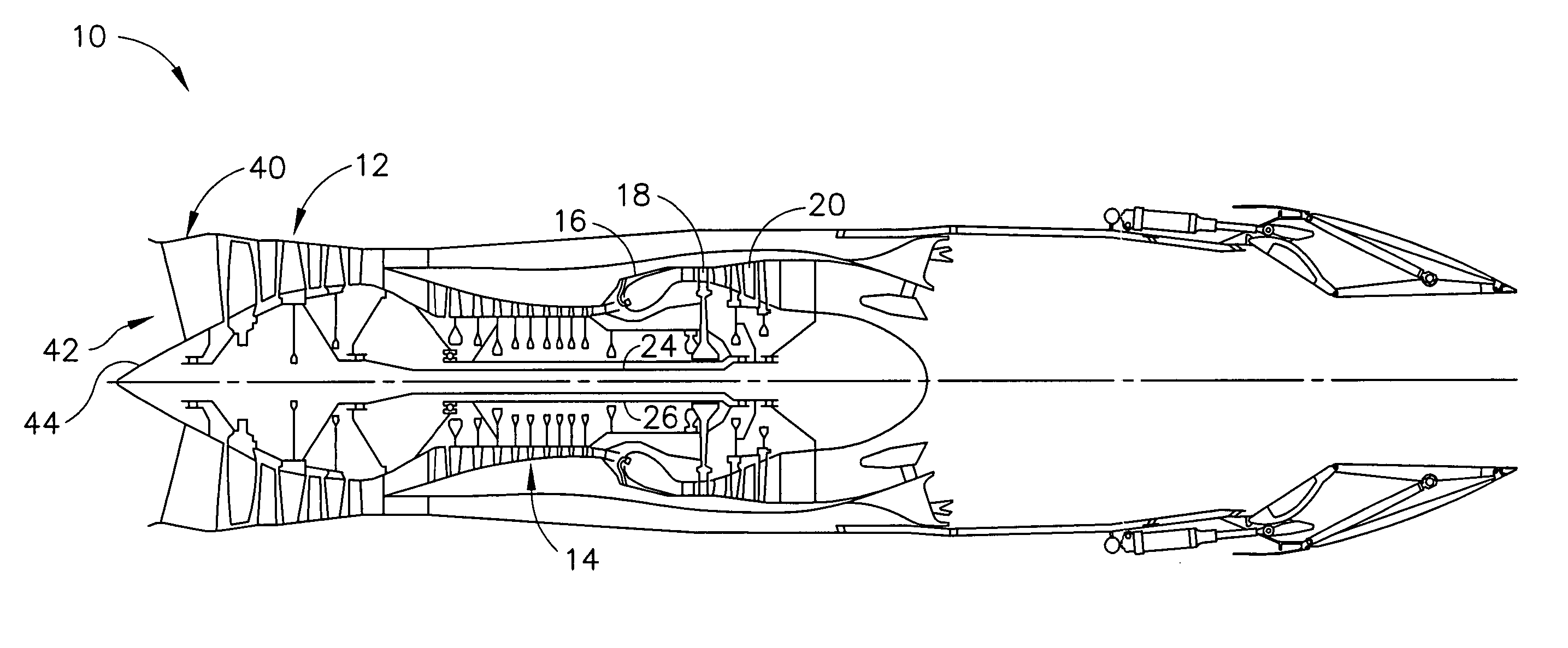
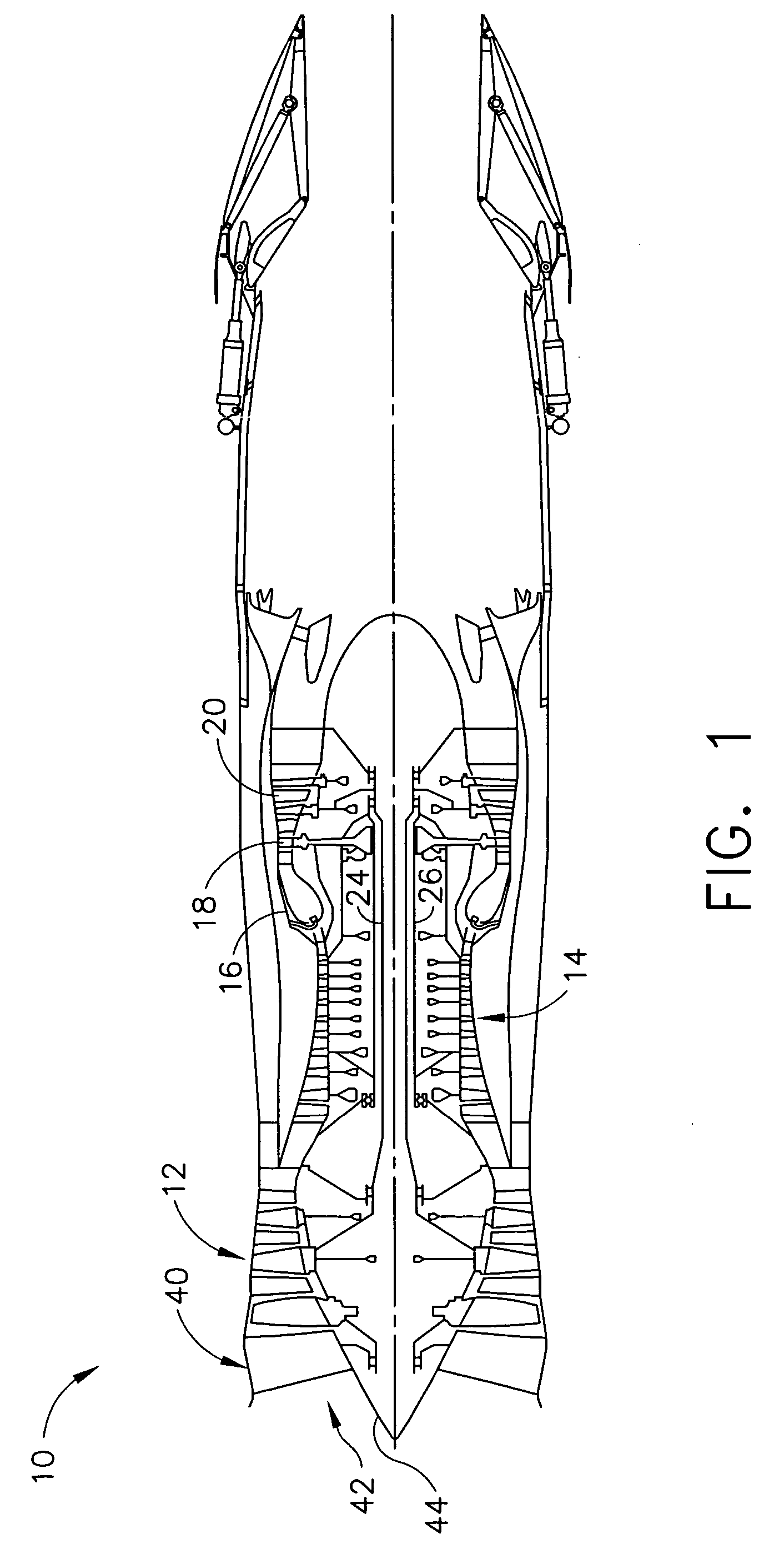
[0010]FIG. 1 is a schematic illustration of a gas turbine engine 10 including a fan assembly 12, a high pressure compressor 14, and a combustor 16. In one embodiment, engine 10 is an F110 engine commercially available from General Electric Company, Cincinnati, Ohio. Engine 10 also includes a high pressure turbine 18 and a low pressure turbine 20, all arranged in a serial, axial flow relationship. Fan assembly 12 and turbine 20 are coupled by a first shaft 24, and compressor 14 and turbine 18 are coupled by a second shaft 26.

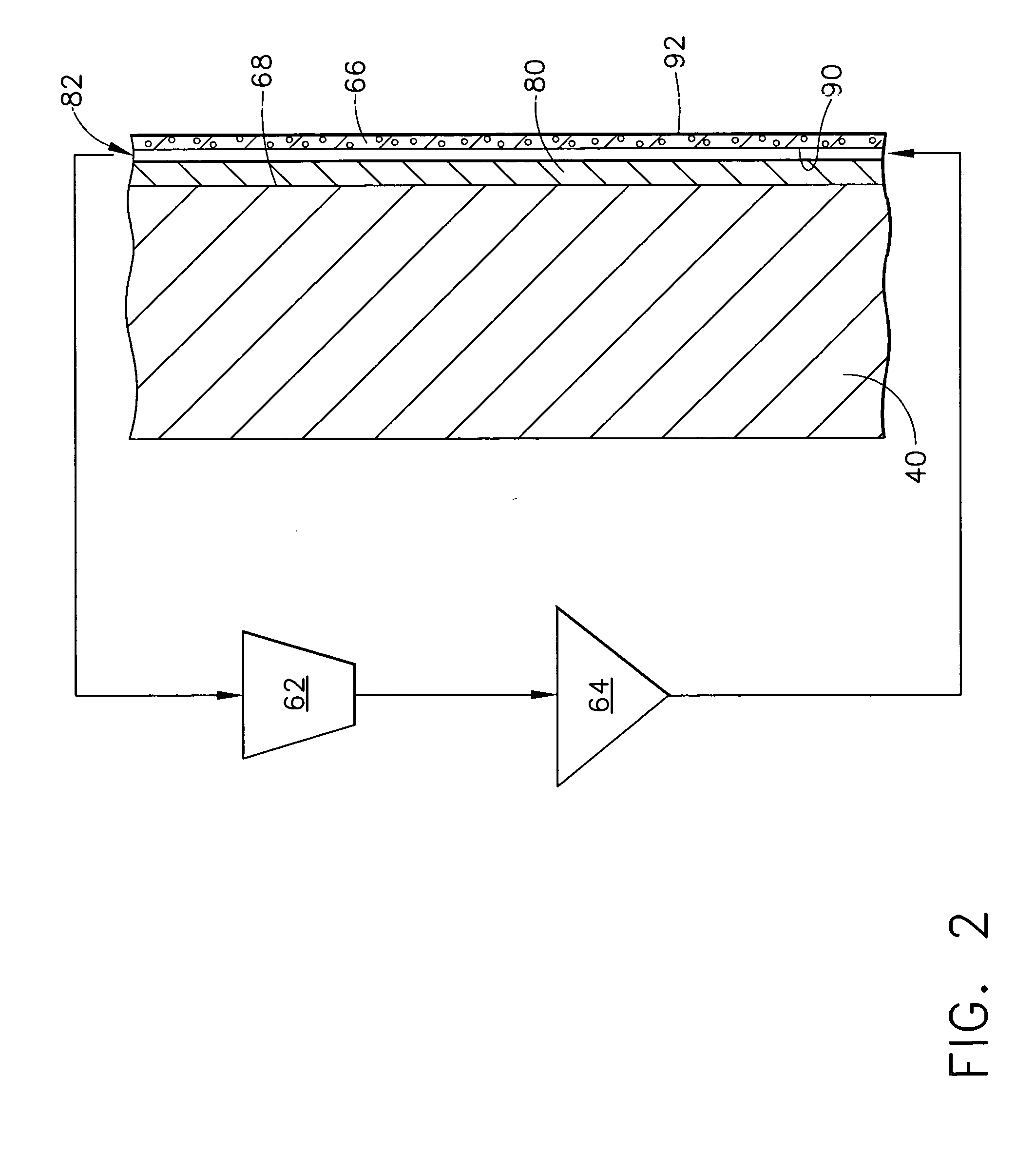
[0011] Engine 10 also includes an annular front frame 40 which supports a bearing (not shown) which, in turn, supports one end of a shaft, such as shaft 24, for allowing rotation thereof. A plurality of circumferentially-spaced inlet guide vane assemblies 42 extend between an outer structural case ring (not shown in FIG. 1) and a center hub 44 and direct airflow entering engine 10 downstream to compressor 14.

[0012] In operation, air flows through inlet guide va...


PUM


Abstract

A method for operating an aircraft engine facilitates preventing ice accumulation on the aircraft engine. The method comprises coupling a semi-permeable membrane to the engine adjacent an outer surface of the engine, coupling a fluid reservoir to the aircraft engine in flow communication with the semi-permeable membrane, and supplying fluid from the fluid reservoir to the semi-permeable membrane to facilitate preventing ice accumulation on the aircraft engine outer surface

Description

BACKGROUND OF THE INVENTION [0001] This invention relates generally to gas turbine engines, and more particularly, to methods and apparatus for operating gas turbine engines. [0002] Gas turbine engines typically include high and low pressure compressors, a combustor, and at least one turbine. The compressors compress air which is mixed with fuel and channeled to the combustor. The mixture is then ignited for generating hot combustion gases, and the combustion gases are channeled to the turbine which extracts energy from the combustion gases for powering the compressor, as well as producing useful work to propel an aircraft in flight or to power a load, such as an electrical generator. [0003] When engines operate in icing conditions, ice may accumulate on exposed external engine structures. More specifically, if engines are operated within icing conditions at low power for extended periods of time, ice accumulation within the engine and over the exposed engine structures may be signi...

Claims


Application Information

Patent Timeline
Patent Type & Authority Applications(United States)
IPC IPC(8): F02C7/047F01D25/02F02K3/02
CPCF01D25/02F02C7/047
Inventor ACKERMAN, JOHN FREDERICKWAGNER, WILLIAM KENT
Owner GENERAL ELECTRIC CO
Why Eureka
Try Eureka