Reflective liquid crystal display device, method of manufacturing the same, and liquid crystal display unit

a liquid crystal display and liquid crystal technology, applied in non-linear optics, instruments, optics, etc., can solve the problems of organic alignment film degraded in the former method, uneven contrast, burn-in, etc., and achieve the effect of long-term reliability

Inactive Publication Date: 2005-03-10
SONY CORP
View PDF2 Cites 17 Cited by
  • Summary
  • Abstract
  • Description
  • Claims
  • Application Information

AI Technical Summary

Benefits of technology

[0027] In view of the foregoing, it is a first object of the invention to provide a reflective liquid crystal display device capable of solving an electrical problem due to the structure of an obliquely evaporated alignment film while maintaining al

Problems solved by technology

If the directions where the liquid crystal molecules are inclined are not uniform during drive, the contrast becomes uneven.
Therefore, there is a problem that the organic alignment film in the former method is degraded due to the light.
Therefore, in the case where a liquid crystal cell is driven for a long time, ions are introduced into the liquid crystal cell, and the deviation of ions occurs in the liquid crystal cell, thereby resulting in so-called burn-in.
However, burn-in occurs because the alignment films formed through oblique evaporation are not dense, so the former technique produces little effect.
Further, the latter technique is not practical, because a problem that new burn-in occurs in an interface between the dielectric layer and the alignment film may arise, or there are problems such as the need for forming a film made of another material in manufacturing.
However, the technique in Japanese Unexamined Patent Application Publication No.
Moreover, the problems such as passage of ions occur in not only a transparent electrode substrate but also a pixel electrode substrate; however, the technique in Japanese Unexamined Patent Application Publication No.
In general, it is difficult to control the alignment of a vertically aligned liquid crystal material.
In the case where there is an uneven structure on the drive substrate by the reflective pixel electrode or the case where a groove exists between pixel electrodes, an alignment defect occurs around the pixel electrode due to the uneven structure.
The alignment d

Method used


Image

  • Reflective liquid crystal display device, method of manufacturing the same, and liquid crystal display unit
  • Reflective liquid crystal display device, method of manufacturing the same, and liquid crystal display unit
  • Reflective liquid crystal display device, method of manufacturing the same, and liquid crystal display unit

Examples


examples

[0124] Next, specific characteristics of the reflective liquid crystal display device according to the embodiment regarding burn-in in a long-term drive will be described referring to examples. Before describing the examples, as comparative examples, the characteristics of a reflective liquid crystal display device of the related art will be described below.

examples 1 and 2

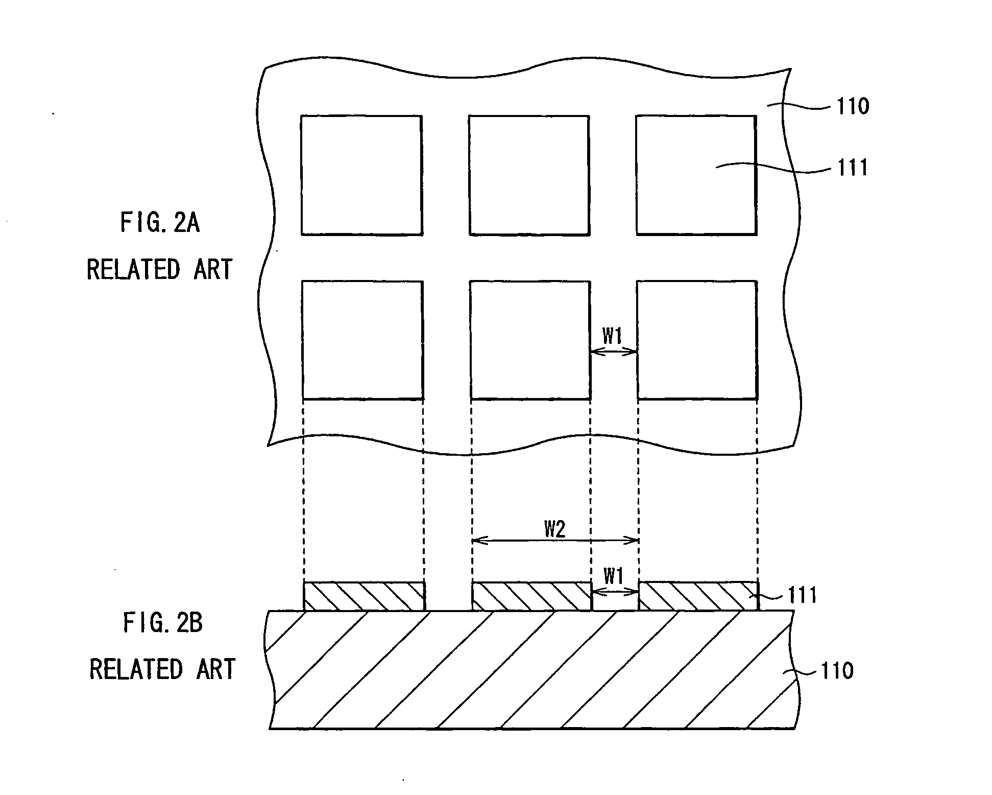
[0128] Next, Examples 1 and 2 will be described below. Basically, test samples of the reflective liquid crystal display device were formed according to the same method and the same specifications as those in the above comparative examples, except for the alignment film on the pixel electrode. More specifically, after a glass substrate on which a transparent electrode was formed and a silicon drive substrate on which an aluminum electrode was formed as a reflective pixel electrode were cleaned, an alignment film was formed through evaporation by a method described below, and then a vertical liquid crystal material with negative dielectric anisotropy Δε manufactured by Merck was injected between the substrates to form a reflective liquid crystal display device as Example 1. The specifications of the silicon drive substrate was the same as those in the above comparative examples, so a pixel pitch was 9 μm and the width of a groove between pixels was 0.6 μm. A reflective liquid crystal ...

examples 3 through 6

[0138] Examples 3 through 6 will be described below. Basically, test samples of the reflective liquid crystal display device were formed according to the same method and the same specifications as those in the above comparative example. More specifically, after a glass substrate on which a transparent electrode was formed and a silicon drive substrate on which an aluminum electrode was formed as a reflective pixel electrode were cleaned, the alignment film was formed on each substrate through evaporation by a method which will be described later, and after that, a vertical liquid crystal material with negative dielectric anisotropy Δε manufactured by Merck was injected between the substrates so as to form each of the test samples of the reflective liquid crystal display device. The specifications of the silicon drive substrate were the same as those of the above comparative examples, and the pixel pitch W2 was 9 μm, and the width of a groove between pixels, that is, the inter-pixel ...


PUM


Abstract

In a reflective liquid crystal display device according to the invention, while maintaining alignment characteristics by an obliquely evaporated alignment film, an electrical problem due to the film structure can be solved, and ions or the like can be prevented from passing through an alignment film, thereby long-term drive reliability can be achieved. Further, misalignment and nonuniform alignment due to the structure of an inter-pixel groove can be prevented so as to achieve superior image quality. In a side of each of a pixel electrode substrate and a transparent electrode substrate closer to a vertically aligned liquid crystal, an obliquely evaporated alignment film is formed on a vertically evaporated film. As the vertically evaporated film is formed as a base film, while maintaining the alignment characteristics of the obliquely evaporated alignment film, an electrical problem due to the film structure can be solved, and ions or the like can be prevented from passing through the obliquely evaporated alignment film so as to achieve long-term reliability. Further, an obliquely evaporated alignment film is formed on a region of the inter-pixel groove through evaporation from an oblique direction with respect to the substrate surface of the pixel electrode substrate, so misalignment and nonuniform alignment due to the structure of the inter-pixel groove can be prevented.

Description

BACKGROUND OF THE INVENTION [0001] 1. Field of the Invention [0002] The present invention relates to a reflective liquid crystal display device comprising a reflective pixel electrode, a method of manufacturing the same, and a liquid crystal display unit such as a reflective liquid crystal projector which displays an image through the use of the reflective liquid crystal display device. [0003] 2. Description of the Related Art [0004] In recent years, with improvement in definition, miniaturization and brightness of projection displays, as display devices of the projection displays, reflective devices capable of reducing their size and displaying with high definition, and being expected to have high light utilization efficiency have become a focus of attention and have been put to practical use. A well-known reflective device is an active type reflective liquid crystal device in which a liquid crystal is injected between a pair of substrates facing each other. In this case, as the pa...

Claims


Application Information

Patent Timeline
IPC IPC(8): G02F1/1335G02F1/1337G02F1/139
CPCG02F1/133553G02F2001/133742G02F1/1393G02F1/133734G02F1/133742G02F1/1337
Inventor HASHIMOTO, SHUNICHIISOZAKI, TADAAKI
Owner SONY CORP
Why Eureka
Try Eureka