Scroll compressor

Inactive Publication Date: 2005-03-10
MITSUBISHI HEAVY IND LTD
View PDF5 Cites 68 Cited by
  • Summary
  • Abstract
  • Description
  • Claims
  • Application Information

AI Technical Summary

Benefits of technology

[0008] It is an object of the present invention to provide a scrol

Problems solved by technology

However, when the bypass hole is provided in a portion that is closer to the outer end of the spiral than the step portion, there is a problem in that a compression loss occurs due to leakage of fluid from an engaging part of the step portion and the wall.
On the other hand, when the

Method used


Image

  • Scroll compressor
  • Scroll compressor
  • Scroll compressor

Examples


first embodiment

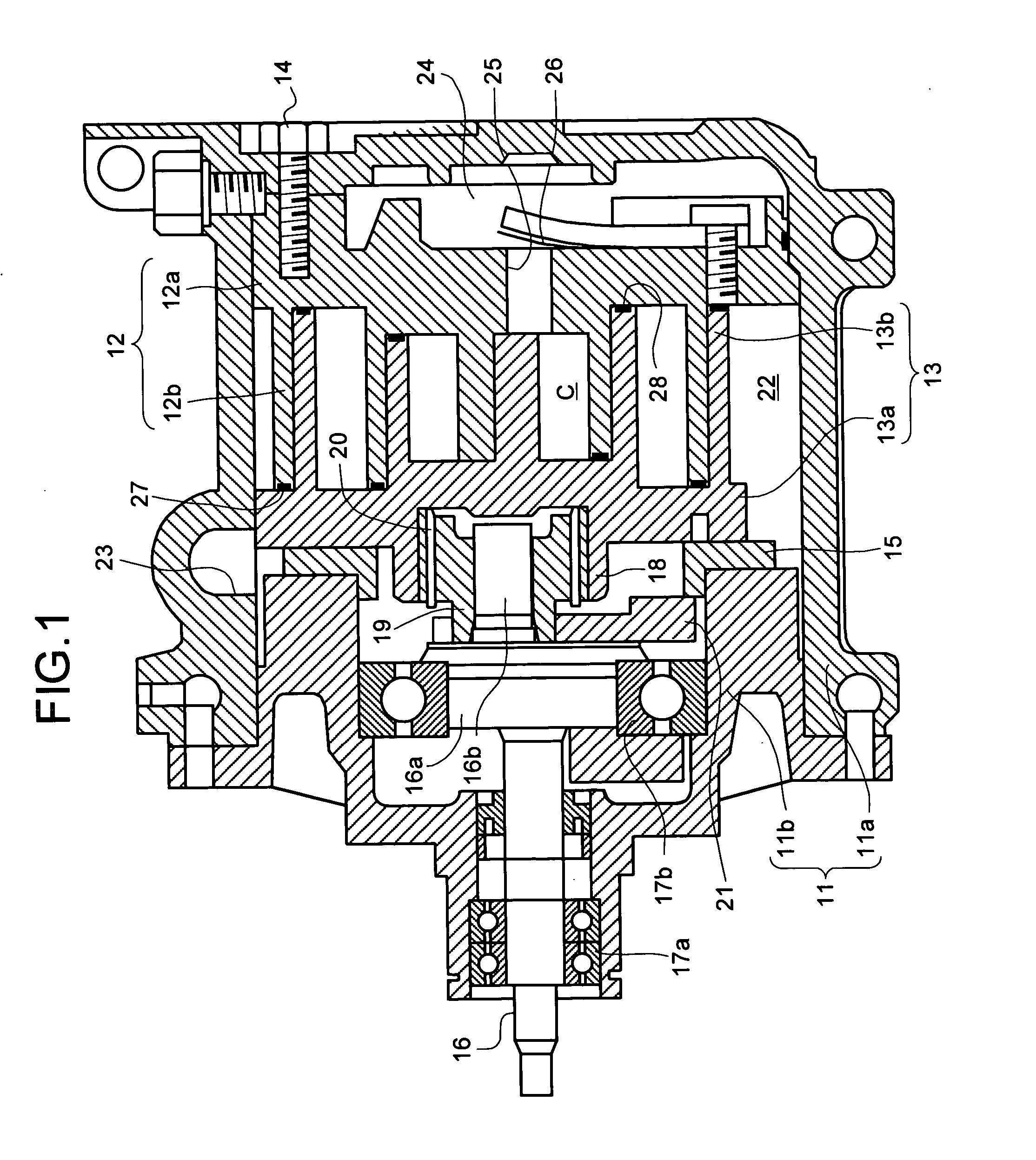
[0026]FIG. 1 is a sectional view of a scroll compressor according to the present invention. This scroll compressor is provided with a scroll compression mechanism that includes a fixed scroll 12 that serves as a first scroll, and a revolving scroll 13 that serves as a second scroll. The fixed scroll 12 and the revolving scroll 13 are housed in a housing 11.

[0027] The housing 11 includes a housing body 11a that is formed in a cup shape, which has an opening, and a lid plate 11b that is fixed to the housing body 11a at the opening.

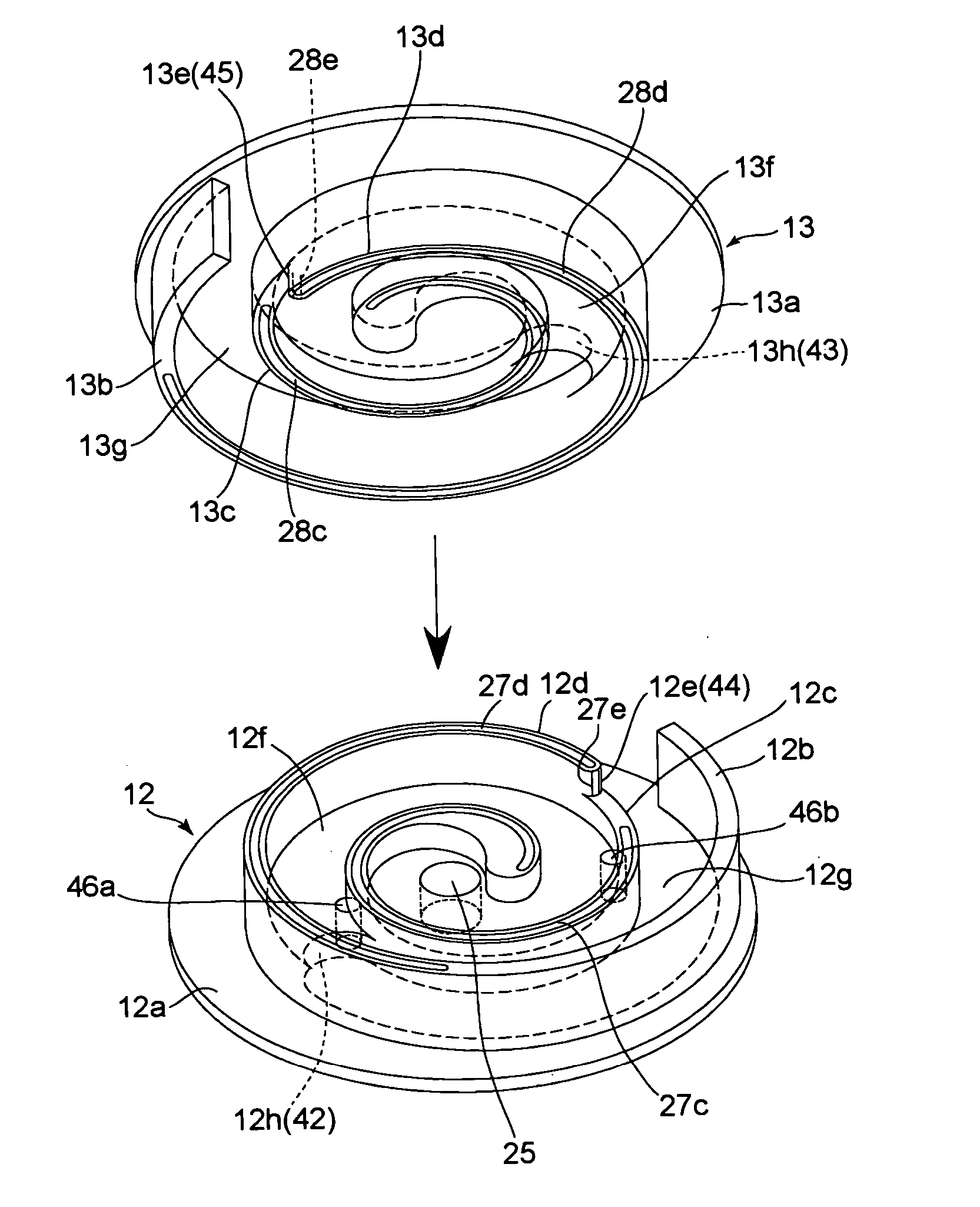
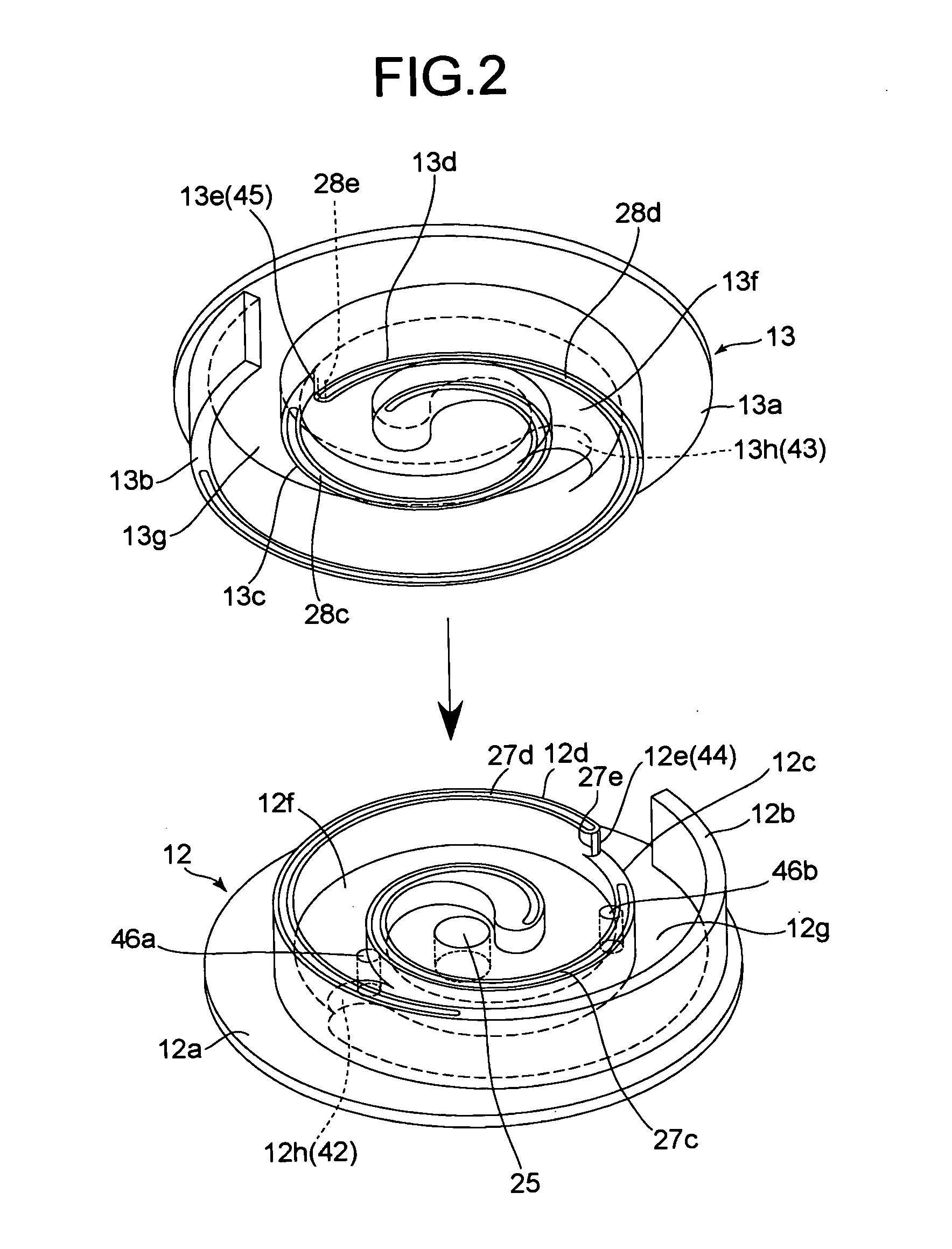
[0028] The fixed scroll 12 includes a spiral wall 12b on a surface of an end plate 12a. The spiral wall 12a is arranged vertically to the end plate 12a. The revolving scroll 13 has substantially a same structure as the fixed scroll 12, and includes a spiral wall 13b on a surface of an end plate 13a. The spiral wall 13a is arranged vertically to the end plate 13a. The wall 12b and the wall 13b are formed in substantially an identical shape.

[0029] The fixed ...

second embodiment

[0053]FIG. 11 is a sectional view of a scroll compressor in a second embodiment according to the present invention. This scroll compressor is provided with a scroll compression mechanism consisting of a fixed scroll 112 serving as a first scroll and a revolving scroll 113 serving as a second scroll in the inside of a housing 111.

[0054] The housing 111 includes a housing body 111a that is formed in a cup shape, which has an opening, and a lid plate 111b that is fixed to the housing body 111a at the opening.

[0055] The fixed scroll 112 includes vertically provided with a spiral wall 112b on a surface of an end plate 112a. The spiral wall 12a is arranged vertically to the end plate 112a. The revolving scroll 113 has substantially a same structure as the fixed scroll 112, and includes a spiral wall 113b on a surface of an end plate 113a. The wall 112b and the wall 113b are formed in substantially an identical shape.

[0056] The fixed scroll 112 is fastened to a bottom inside the cup shap...


PUM


Abstract

A scroll compressor includes a first scroll and a second scroll. The first scroll has a step portion that separates an elevated portion and a recessed portion of a surface of the first scroll. A spiral wall of the second scroll has a step that separates an elevated portion and a recessed portion of the wall. A first bypass hole is provided in the elevated portion of the surface of the first scroll. A second bypass hole is provided in the recessed portion of the surface of the first scroll. The second bypass hole is within 360 degrees toward a center of the spiral of the first scroll from an outer end of the spiral. The first bypass hole is within 360 degrees from the second bypass hole toward the center of the spiral.

Description

BACKGROUND OF THE INVENTION [0001] 1) Field of the Invention [0002] The present invention relates to a scroll compressor in an air conditioning apparatus, a refrigerating apparatus, and the like. [0003] 2) Description of the Related Art [0004] A scroll compressor includes a fixed scroll and a revolving scroll. The fixed scroll includes a spiral wall that is vertically fixed to an end plate. The revolving scroll also includes a spiral wall, which has substantially the same shape as the wall of the fixed scroll, that is vertically fixed to another end plate. The scroll compressor is assembled in such a manner that the walls of the fixed scroll and the revolving scroll engage with each other. In this state, the revolving scroll is revolved with respect to the fixed scroll, whereby a volume of a compression chamber formed between the walls is gradually reduced to compress fluid in the compression chamber. [0005] Some conventional scroll compressors are provided with a step portion betwe...

Claims


Application Information

Patent Timeline
IPC IPC(8): F04C18/02F04C28/26
CPCF04C18/0215F04C18/0261F04C28/26F04C18/088F04C18/0276F04C18/02
Inventor TAKEUCHI, MAKOTOUKAI, TETSUZOTOKUDA, MASAAKI
Owner MITSUBISHI HEAVY IND LTD
Why Eureka
Try Eureka