Network repeater apparatus, network repeater method and network repeater program

Inactive Publication Date: 2005-03-17
FUJITSU LTD
View PDF4 Cites 110 Cited by
  • Summary
  • Abstract
  • Description
  • Claims
  • Application Information

AI Technical Summary

Benefits of technology

[0043] Moreover, the network repeater program according to the present invention serves to make the computer further perform: a storage step of storing the addresses before and after the translation in the first address translation step in a prescribed storage area in association with each other; and a second address translation step of translating, upon input of a reply packet to the communication packet, a destination of the reply packet to the communication packet based on data stored in the storage area.

Problems solved by technology

In addition, according to conventional methods, when access is made to a common device, it is necessary for the common device to provide a plurality of interfaces or a plurality of network addresses, or complicated settings such as conducting a plurality of settings in a DNS server for name resolution, or it is necessary to access the common device by way of an external network.

Method used


Image

  • Network repeater apparatus, network repeater method and network repeater program
  • Network repeater apparatus, network repeater method and network repeater program
  • Network repeater apparatus, network repeater method and network repeater program

Examples


embodiment 1

[0061] Now, preferred embodiments of the present invention will be described below in detail while referring to the accompanying drawings.

first embodiment

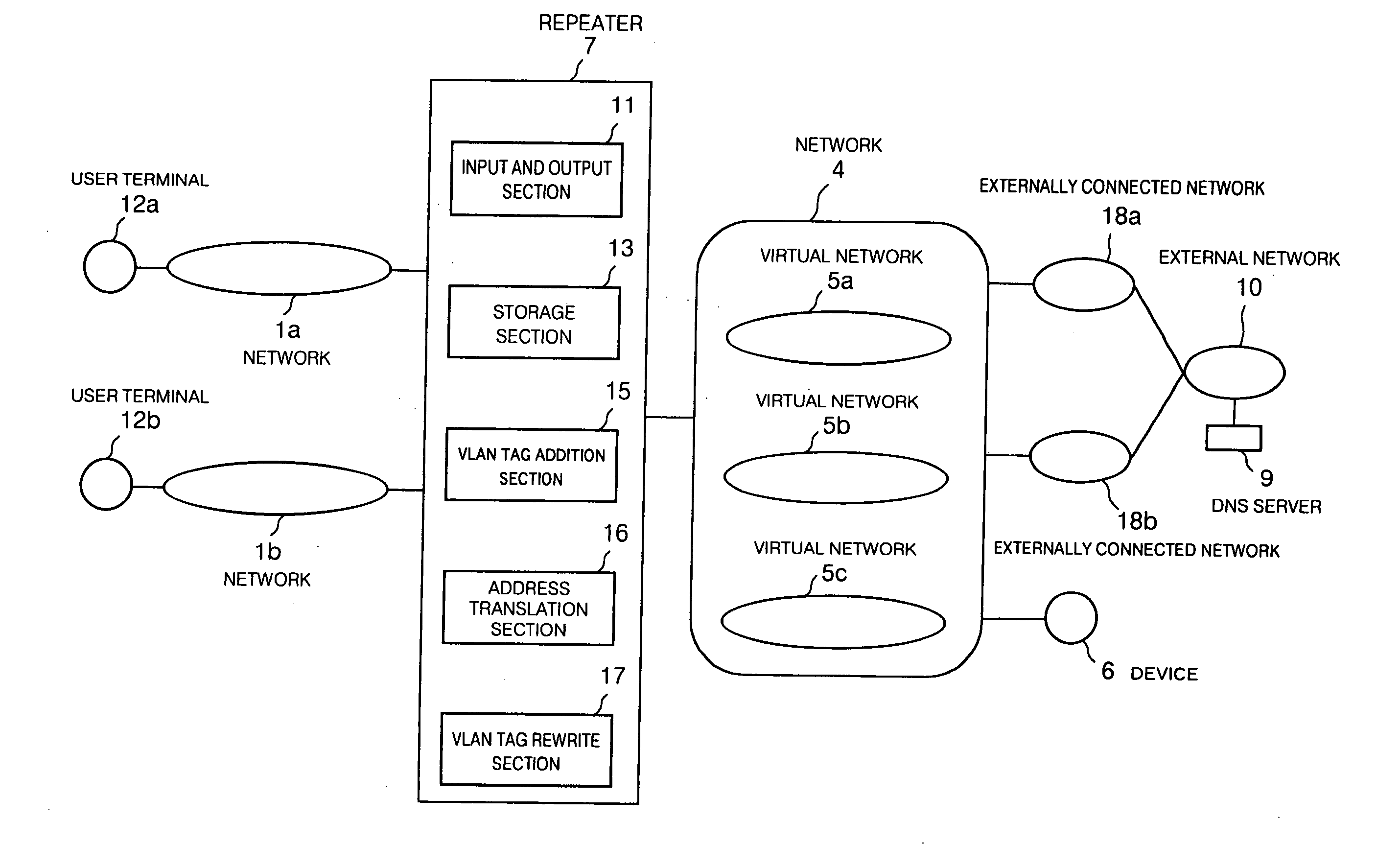
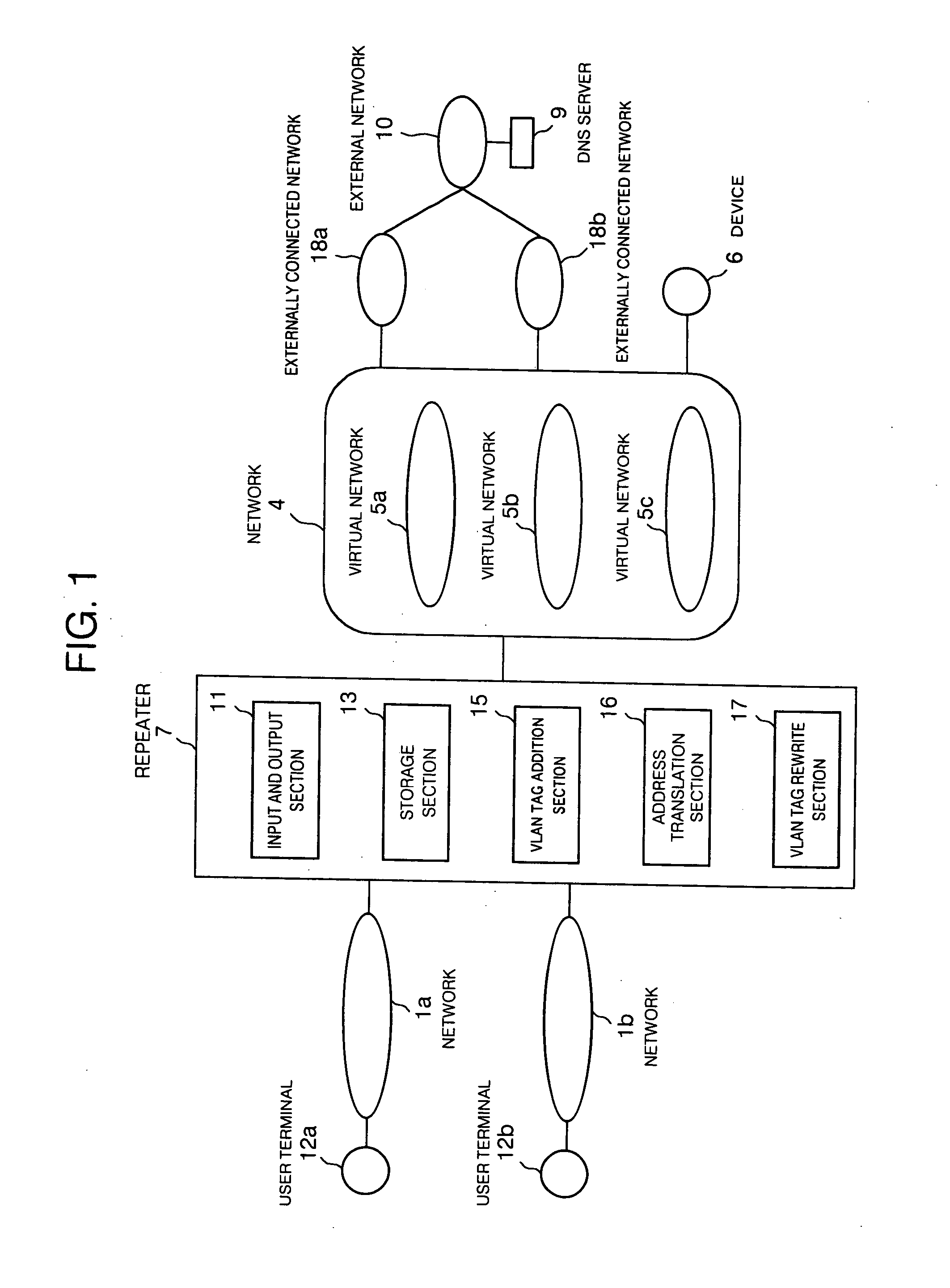
[0062]FIG. 1 is a view that shows the outline of a network repeater technique according to the present invention. This view illustrates a configuration similar, except for a repeater, to the above-mentioned one of FIG. 12 showing the prior art. As shown in this figure, the repeater 7 includes an input and output section 11 in the form of an I / O interface between a variety of networks, a storage section 13 that stores various data, a VLAN tag addition section 15 that adds VLAN tags to input communication packets, an address translation section 16 that translates the source addresses of input communication packets, and a VLAN tag rewrite section 17 that rewrites VLAN tags added by the VLAN tag addition section 15.

[0063] Describing the outline of the processing according to this embodiment, communication packets from networks 1a, 1b connected to the repeater 7 are distributed to virtual networks 5a, 5b, as shown in FIG. 1. When the destination of each communication packet is a commonly...

embodiment 2

[0075] In cases where the wholesale provider provides services from the common device 6 to the users who contract with the provider, in order to enable the device 6 to be accessed so as to accommodate the users in the virtual networks different according to the individual ISPs while keeping network security, according to conventional techniques, the device 6 has to be connected to the individual virtual networks with separate addresses, respectively, or the device 6 has to once access the individual virtual networks by way of an external network (the Internet). According to the present invention, however, by properly adding a VLAN tag to a communication packet input to the repeater and translating the source address thereof, it is possible to make access to the common device while keeping security between the networks without generating unnecessary traffic due to passing through external networks as well as without performing complicated settings such as setting a plurality of discr...


PUM


Abstract

A network repeater apparatus connected to a plurality of networks is provided which includes a VLAN tag addition section (15) or a VLAN tag rewrite section (17) that performs prescribed VLAN tag processing with respect to a communication packet based on prescribed information of the communication packet when the communication packet is input from any one among a plurality of networks, an address translation section (16) that translates a source address of the communication packet based on the prescribed information, and an input and output section (11) that outputs to a prescribed virtual network a communication packet which has been subjected to at least either one of processing by the VLAN tag addition section (15) or the VLAN tag rewrite section (17) or address translation by the address translation part (16), whereby access can be made to a common device while ensuring security between the networks.

Description

TECHNICAL FIELD [0001] The present invention relates to a repeater technique, a security technique and a service providing environment construction technique for communication networks, and more particularly, it relates to a network repeater apparatus, a network repeater method and a network repeater program which are excellent in application to network repeaters such as hubs, switches, bridges, routers and so on, server devices for providing services, distribution devices for distributing access to services, and authentication devices for performing user authentication. BACKGROUND ART [0002] Under the environments in which there are a plurality of different networks which are undesirable to be mutually accessed from one another for the reasons of security or the like, e.g., environments where there are a plurality of networks in each of units such as organizations like enterprises, schools, etc., or environments where there are a plurality of networks in each of users or communicat...

Claims


Application Information

Patent Timeline
Patent Type & Authority Applications(United States)
IPC IPC(8): H04L12/46H04L29/12
CPCH04L12/4666H04L61/2514H04L29/12367H04L29/12009H04L61/00
Inventor OKANO, TETSUYATAKEYAMA, AKIRANARITOMI, TOSHIHIKO
Owner FUJITSU LTD
Why Eureka
Try Eureka