Network repeater apparatus, network repeater method and network repeater program

a network repeater and repeater technology, applied in the field of network repeater apparatus, network repeater method and network repeater program, to achieve the effect of reducing the load on the input network side, facilitating access to the common device, and ensuring security

Inactive Publication Date: 2008-11-11
FUJITSU LTD
View PDF9 Cites 2 Cited by
  • Summary
  • Abstract
  • Description
  • Claims
  • Application Information

AI Technical Summary

Benefits of technology

[0014]According to such a configuration, even in cases where security between the networks is ensured by the use of a VLAN, it becomes possible to make access to a common device from each network by performing processing corresponding to the common device on the communication packet for its VLAN tag as well as appropriate processing on its source address. In addition, according to conventional methods, when access is made to a common device, it is necessary for the common device to provide a plurality of interfaces or a plurality of network addresses, or complicated settings such as conducting a plurality of settings in a DNS server for name resolution, or it is necessary to access the common device by way of an external network. In contrast to this, according to the present invention, such complicated settings are unnecessary and there is no need to pass through an external network, so it is possible to prevent the generation of unnecessary or wasteful traffic as well as the reduction in throughput.
[0036]According to such a configuration, the network repeater apparatus can directly receive a connection request from a user terminal and perform an authentication operation. As a result, communication packets can be immediately accommodated into the virtual network from the user terminal, so the load on the input network side is reduced. For example, in wholesale providers or the like, security is conventionally ensured consistently from the time of authentication by integrating user authentication functions, but when a common device is accessed, it is necessary to adopt a technique of providing an interface for each network in the common device or it is necessary to release the security once ensured. With this configuration, however, such a problem can be solved, thus making it possible to ensure security and access the common device more easily. In a preferred embodiment of the present invention, the authentication part corresponds to an authentication section.

Problems solved by technology

In addition, according to conventional methods, when access is made to a common device, it is necessary for the common device to provide a plurality of interfaces or a plurality of network addresses, or complicated settings such as conducting a plurality of settings in a DNS server for name resolution, or it is necessary to access the common device by way of an external network.

Method used


Image

  • Network repeater apparatus, network repeater method and network repeater program
  • Network repeater apparatus, network repeater method and network repeater program
  • Network repeater apparatus, network repeater method and network repeater program

Examples


embodiment 1

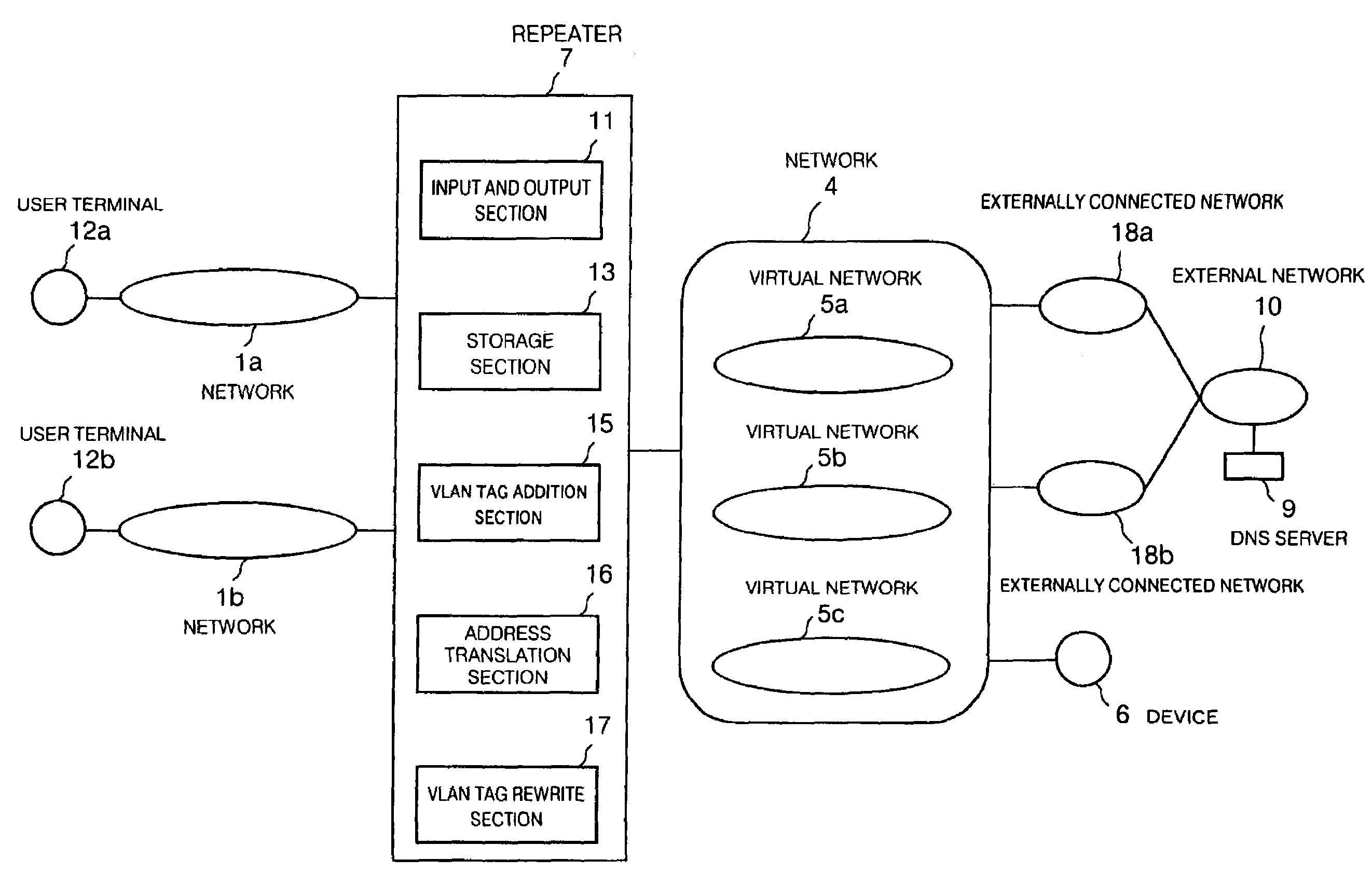
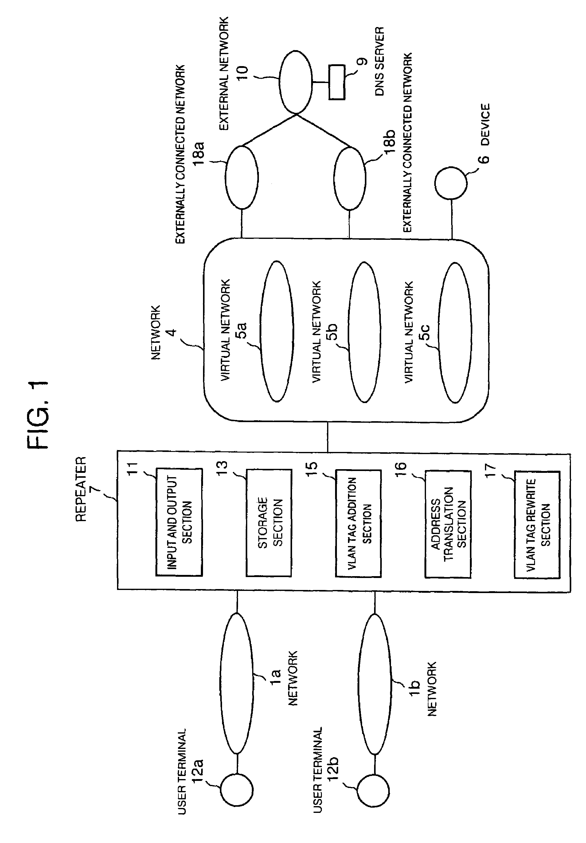
[0063]FIG. 1 is a view that shows the outline of a network repeater technique according to a first embodiment of the present invention. This view illustrates a configuration similar, except for a repeater, to the above-mentioned one of FIG. 12 showing the prior art. As shown in this figure, the repeater 7 includes an input and output section 11 in the form of an I / O interface between a variety of networks, a storage section 13 that stores various data, a VLAN tag addition section 15 that adds VLAN tags to input communication packets, an address translation section 16 that translates the source addresses of input communication packets, and a VLAN tag rewrite section 17 that rewrites VLAN tags added by the VLAN tag addition section 15.

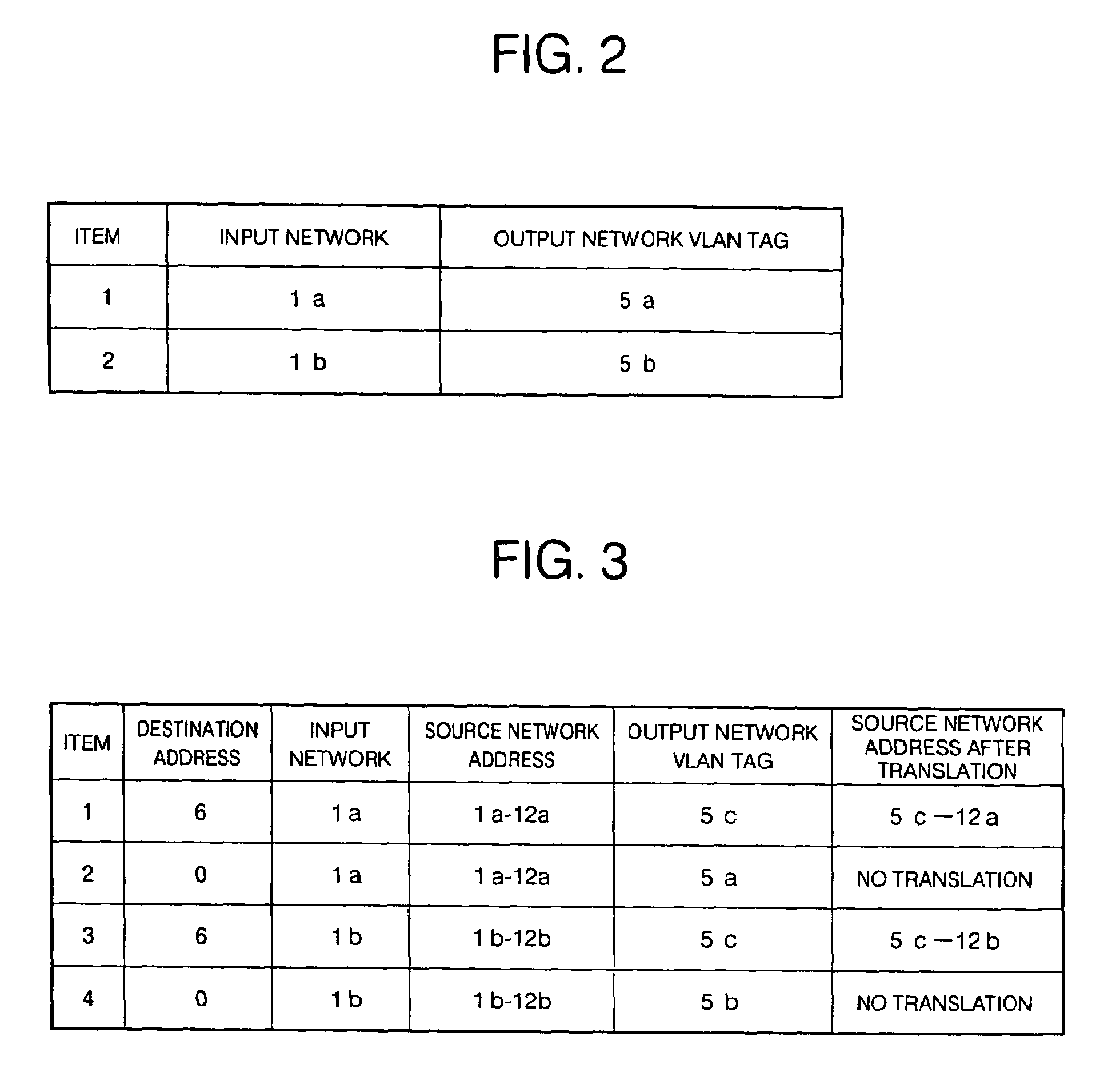
[0064]Describing the outline of the processing according to this embodiment, communication packets from networks 1a, 1b connected to the repeater 7 are distributed to virtual networks 5a, 5b, as shown in FIG. 1. When the destination of each communication...

embodiment 2

[0077]This embodiment is substantially similar in configuration to the first embodiment, but shows the case where connected networks are virtual networks. Specifically, the connected networks are already virtual networks, so communication packets not addressed to a common device can be output to the same virtual network as an input network, but they can of course be translated into new virtual networks.

[0078]FIG. 5 is a view that schematically illustrates this embodiment.

[0079]A VLAN tag addition section 15 of a repeater 7 verifies whether a VLAN tag has already been added to an input communication packet. If networks 2a, 2b in the figure are virtual networks to which VLAN tags have already been added or attached, it is determined that VLAN tags were added to these networks, and tag addition processing is not performed. Here, note that the VLAN tag is not rewritten when the communication packet is output to the same virtual network as the input network, whereas the VLAN tag is rewri...

embodiment 3

[0085]In this embodiment, reference will be made to the case where among the above-mentioned functions of the repeater apparatus, a part having the function of the VLAN tag addition section and a part having the function of the address translation section and the function of the VLAN tag rewrite section are provided as mutually separate devices for performing network repeating operation.

[0086]FIG. 8 is a view that schematically illustrates this embodiment.

[0087]The configuration of this embodiment is similar to that of FIG. 1 other than the repeater. The repeater 7 in FIG. 1 corresponds to a repeater 7a and an address translation device 7b in FIG. 8. As illustrated in these figures, the repeater 7a includes an input and output section 11a, a storage section 13a and a VLAN tag addition section 15. The address translation device 7b includes an input and output section 11b, a storage section 13b, an address translation section 16 and a VLAN tag rewrite section 17.

[0088]The technique of...


PUM


Abstract

A network repeater apparatus connected to a plurality of networks is provided which includes a VLAN tag addition section (15) or a VLAN tag rewrite section (17) that performs prescribed VLAN tag processing with respect to a communication packet based on prescribed information of the communication packet when the communication packet is input from any one among a plurality of networks, an address translation section (16) that translates a source address of the communication packet based on the prescribed information, and an input and output section (11) that outputs to a prescribed virtual network a communication packet which has been subjected to at least either one of processing by the VLAN tag addition section (15) or the VLAN tag rewrite section (17) or address translation by the address translation part (16), whereby access can be made to a common device while ensuring security between the networks.

Description

[0001]This application is a continuing application, filed under 35 U.S.C. §111(a), of International Application PCT / JP02 / 04843, filed May 20, 2002.TECHNICAL FIELD[0002]The present invention relates to a repeater technique, a security technique and a service providing environment construction technique for communication networks, and more particularly, it relates to a network repeater apparatus, a network repeater method and a network repeater program which are excellent in application to network repeaters such as hubs, switches, bridges, routers and so on, server devices for providing services, distribution devices for distributing access to services, and authentication devices for performing user authentication.BACKGROUND ART[0003]Under the environments in which there are a plurality of different networks which are undesirable to be mutually accessed from one another for the reasons of security or the like, e.g., environments where there are a plurality of networks in each of units...

Claims


Application Information

Patent Timeline
Patent Type & Authority Patents(United States)
IPC IPC(8): H04L12/28H04L12/46H04L29/12
CPCH04L12/4666H04L29/12009H04L29/12367H04L61/2514H04L61/00
Inventor OKANO, TETSUYATAKEYAMA, AKIRANARITOMI, TOSHIHIKO
Owner FUJITSU LTD
Why Eureka
Try Eureka