Scaffold safety railing device

a safety railing and scaffolding technology, applied in scaffold accessories, manufacturing tools, building scaffolds, etc., can solve the problems of cumbersome use, time-consuming reset and repositioning of devices, and failure to provide a quick and easy way for workers to quickly reposition and reset safety rails relative to repositioned scaffolds

Active Publication Date: 2005-03-24
MORRIS MICHAEL JOHN
View PDF5 Cites 13 Cited by
  • Summary
  • Abstract
  • Description
  • Claims
  • Application Information

AI Technical Summary

Benefits of technology

[0006] It is therefore an object of the present invention to provide a support clamp device for a safety rail or similar device adapted for mounting on a pump jack pole comprising a first pole clamp, circumscribing a generally rectangular perimeter, the first pole clamp comprising a generally U-shaped bar having a first side; a second side and a third side, wherein the first and third sides are approximately parallel to each other and the second side is approximately perpendicular to the first and third sides and wherein the second side further comprises an aperture; and a fourth side removably attached to the first and third sides opposite and approximately parallel the second side; and a second pole clamp, circumscribing a generally rectangular perimeter, the ...

Problems solved by technology

In most cases, however, these devices are cumbersome to use and take time to reset and reposition.
While useful for providing a worker with a safer environment while working on a scaffold platform, they fail to provide a quick and easy way for a worker to rapidly reposition and reset the safety rail relative to a repositioned scaffold, particularly in the vertical plane and at various particular vertical positions.
In particular, the prior ...

Method used


Image

  • Scaffold safety railing device
  • Scaffold safety railing device
  • Scaffold safety railing device

Examples


Embodiment Construction

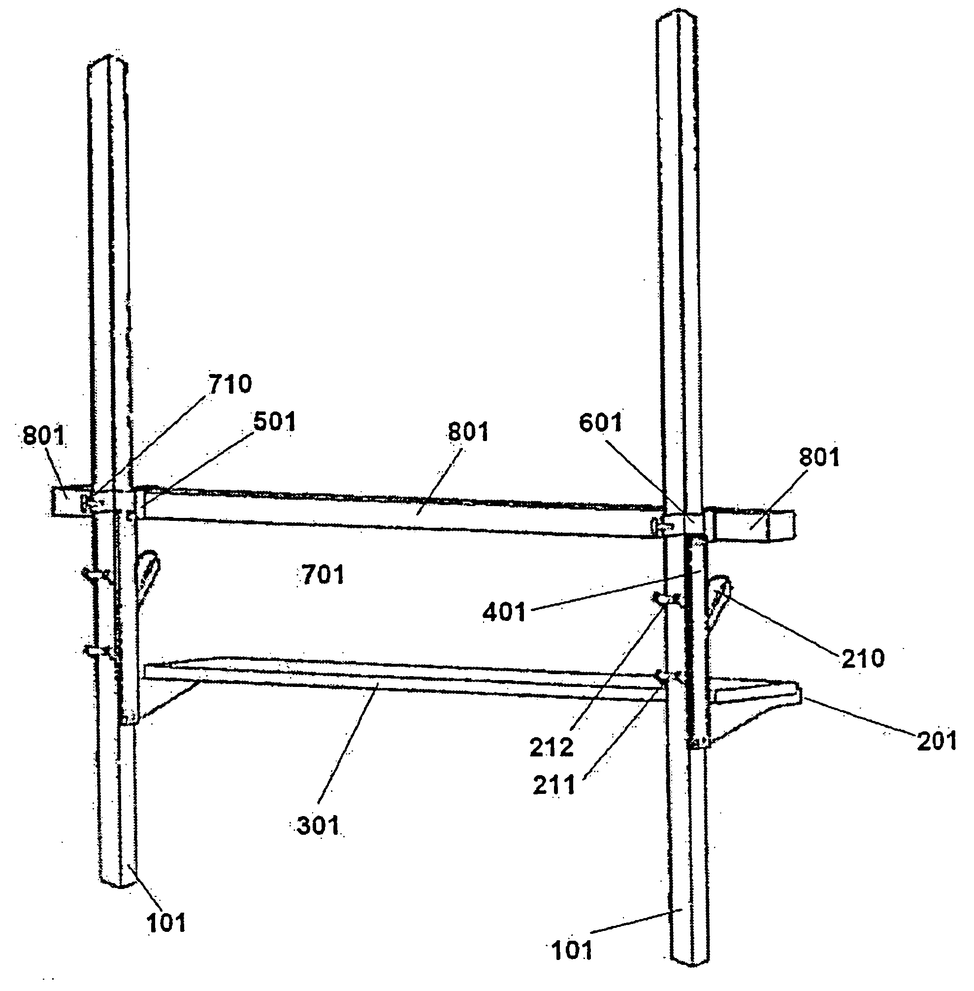
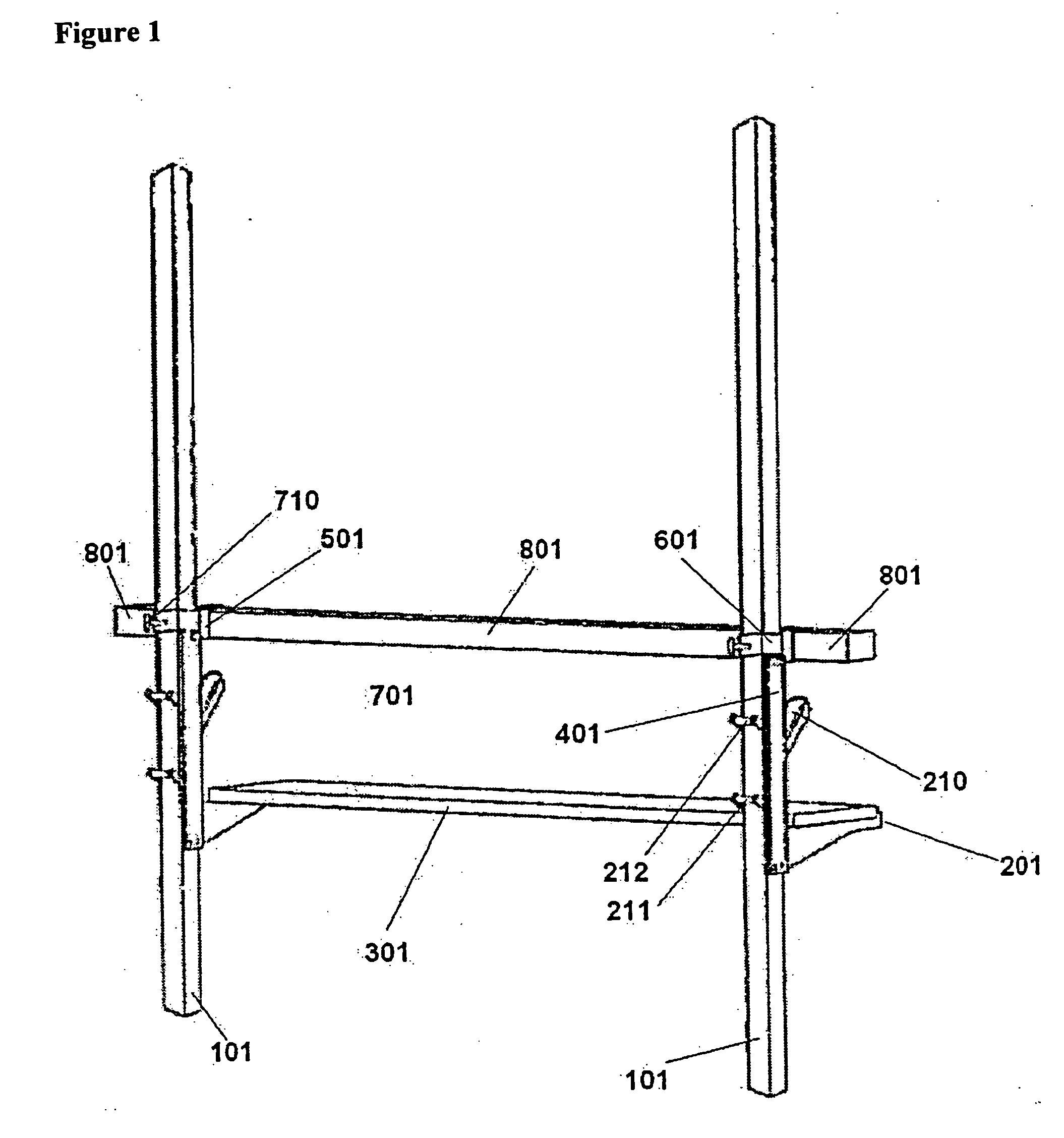
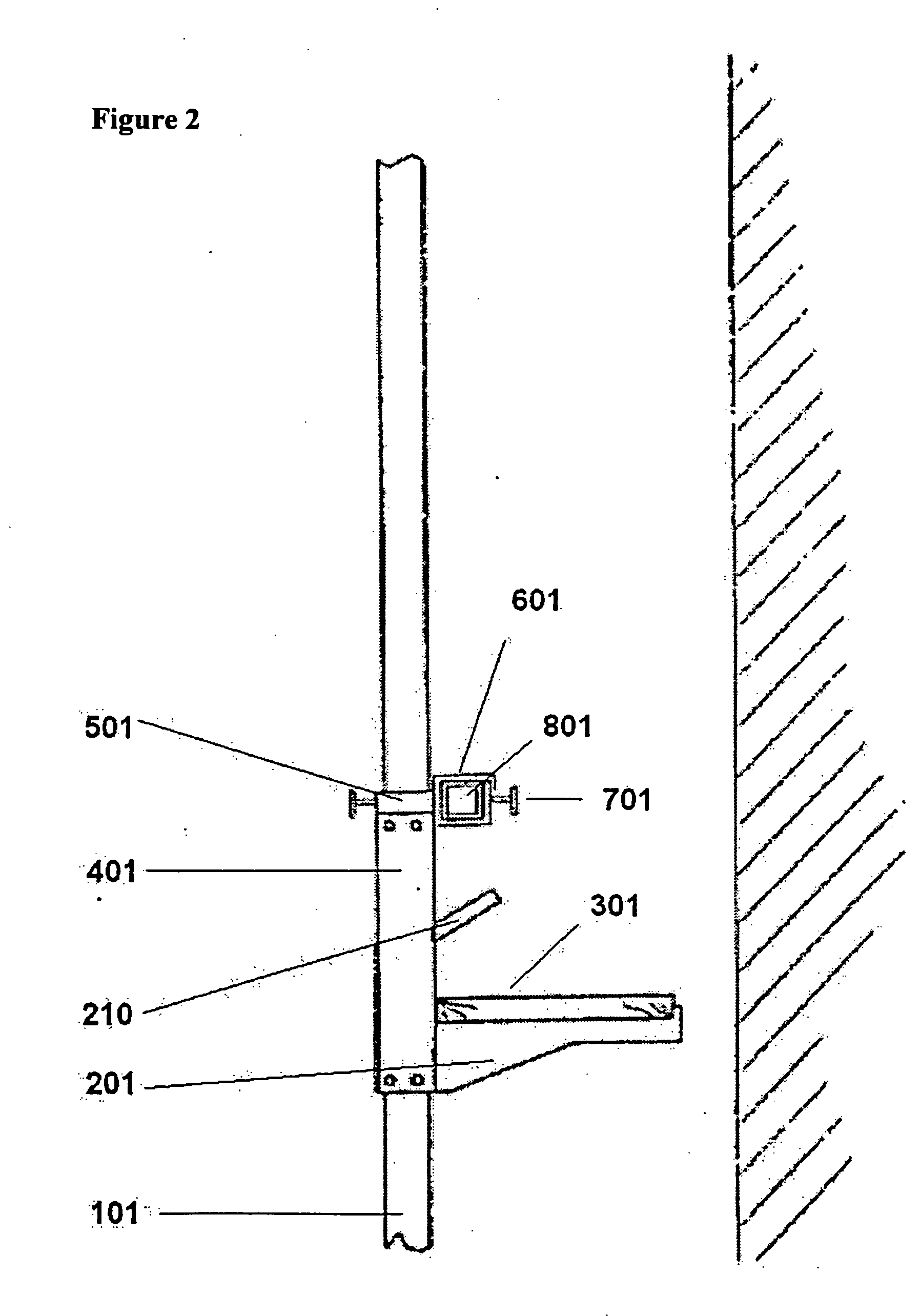
[0012] The present invention provides a support clamp device for a scaffold safety rail device adapted for mounting on a pump jack pole comprising a first pole clamp, circumscribing a generally rectangular perimeter, the first pole clamp comprising a generally U-shaped bar having a first side; a second side and a third side, wherein the first and third sides are approximately parallel to each other and the second side is approximately perpendicular to the first and third sides and wherein the second side further comprises an aperture; and a fourth side removably attached to the first and third sides opposite and approximately parallel the second side; and a second pole clamp, circumscribing a generally rectangular perimeter, the second pole clamp comprising a generally U-shaped bar having a first side; a second side and a third side, wherein the first and third sides are approximately parallel to each other and the second side is approximately perpendicular to the first and third si...


PUM


Abstract

The present invention provides a support clamp device for a safety rail or similar device adapted for mounting on a pump jack pole comprising: a first pole clamp, circumscribing a generally rectangular perimeter, the first pole clamp comprising a generally U-shaped bar having a first side; a second side and a third side, wherein the first and third sides are approximately parallel to each other and the second side is approximately perpendicular to the first and third sides and wherein the second side further comprises an aperture; and a fourth side removably attached to the first and third sides opposite and approximately parallel the second side; and a second pole clamp, circumscribing a generally rectangular perimeter, the second pole clamp comprising a generally U-shaped bar having a first side; a second side and a third side, wherein the first and third sides are approximately parallel to each other and the second side is approximately perpendicular to the first and third sides and wherein the second side further comprises an aperture; and a fourth side removably attached to the first and third sides opposite and approximately parallel the second side; and a pole clamp connecting fastening means stably inserted through the aperture of the second side of the first pole clamp and through the aperture of the second side of the second pole clamp, wherein the first pole clamp and the second pole clamp are able to pivotably rotate about the axis formed by the pole clamp connecting fastener.

Description

[0001] Throughout this application, various publications are referenced. Full citations for these publications may be found listed at the end of the specification and preceding the Claims. The disclosures of these publications in their entireties are hereby incorporated by reference into this application in order to more fully describe the state of the art. FIELD OF THE INVENTION [0002] The present invention involves the field of scaffolding devices in general and specifically relates to a method and device for securing a safety rail to a scaffold support. According to an embodiment of this invention, the device comprises a metal coupling device. The invention further comprises pivotable connector permitting two coupling devices to be joined in perpendicular planes. According to a further embodiment of the invention, a vertical spacer provides stabilization in the vertical plane. According to a preferred embodiment of the invention the coupling device is capable of stably positionin...

Claims


Application Information

Patent Timeline
IPC IPC(8): E04G1/20E04G1/38E04G5/14
CPCE04G1/20Y10T403/7105E04G5/14E04G1/38
Inventor MORRIS, MICHAEL JOHN
Owner MORRIS MICHAEL JOHN
Why Eureka
Try Eureka