
Method and apparatus for displaying image and computer-readable recording medium for storing computer program

a computer program and recording medium technology, applied in the field of display devices, can solve the problems of increasing image blurring, color fringe, and the above-described image display method and apparatus are not suitable for a mobile environment, and achieve the effect of reducing color fring

Active Publication Date: 2005-03-24
SAMSUNG ELECTRONICS CO LTD
View PDF25 Cites 27 Cited by
  • Summary
  • Abstract
  • Description
  • Claims
  • Application Information

AI Technical Summary

Benefits of technology

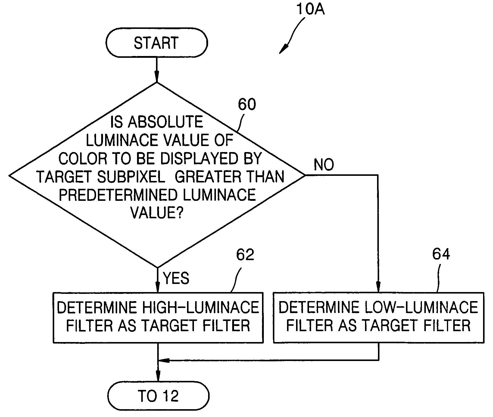
The present invention provides a method, apparatus, and computer-readable recording medium for performing subpixel rendering to minimize color fringe in image displays. This involves adjusting the target phase of a subpixel based on the difference between the absolute luminance value of the color to be displayed and the adjacent subpixel, and obtaining a relative luminance value for the target subpixel from the surrounding image pixels using a target filter with the adjusted target phase as its center. The brightness of the color displayed by the target subpixel is determined based on the relative luminance value. This invention allows for improved image quality and reduced color fringe in image displays.

Problems solved by technology

However, a color image displayed on the conventional image display apparatus displaying an image by subpixel rendering may have a color fringe due to a phase shift of subpixels when a brightness value rapidly changes among the subpixels at a boundary of the color image.
However, such a conventional image display method and apparatus in which a subpixel of interest is expressed by an average of adjacent image pixels have disadvantages of increasing image blurring and causing a color fringe when brightness rapidly changes among chrominance components.
However, since the optimal filter is designed in consideration of the theoretical visibility range, the above-described image display method and apparatus are not suitable for a mobile environment, i.e., when a fluid visibility range needs to be secured to display an image.
Moreover, since the conventional image display method and apparatus use the filter designed to operate in an opponent color space, unnecessary complex color space conversion is required.
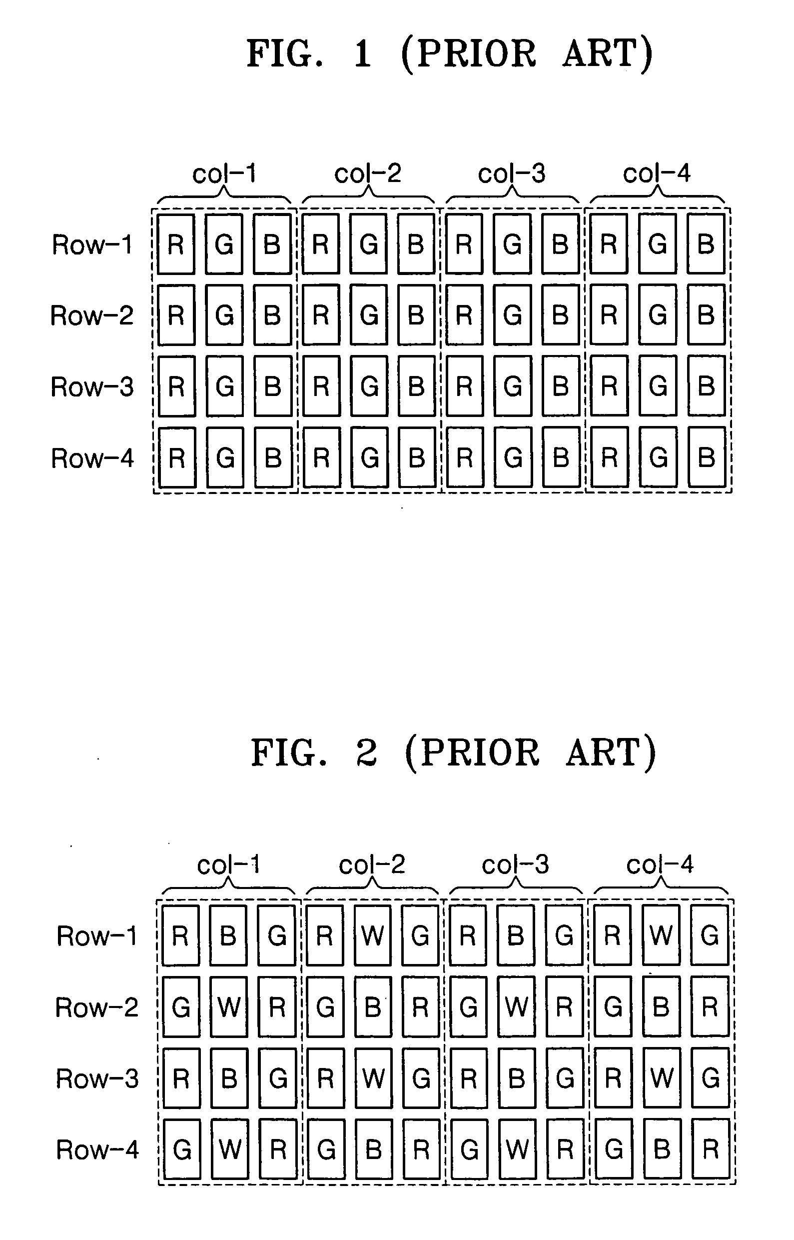
In addition, in the conventional image display methods and apparatuses, each subpixel displays only one among three colors, as shown in FIG. 1, but a high-resolution color image cannot be displayed without a color fringe when each subpixel displays one among four colors, as shown in FIG. 2, or one among more than four colors.

Method used


Image

  • Method and apparatus for displaying image and computer-readable recording medium for storing computer program
  • Method and apparatus for displaying image and computer-readable recording medium for storing computer program
  • Method and apparatus for displaying image and computer-readable recording medium for storing computer program

Examples


first embodiment

[0048] According to the present invention, when an adjacent subpixel displays color having a high absolute luminance value, a target phase may be shifted such that a distance between the target phase and the center of gravity of the adjacent subpixel becomes farther. The center of gravity indicates the center of an area occupied by a subpixel in physical space. For example, when an adjacent subpixel displays white, a target phase must be shifted such that a distance between the target phase and the center of gravity of the adjacent subpixel displaying white becomes larger in order to reduce a color fringe. However, when the target phase is shifted too far from the center of gravity of the adjacent subpixel, a resolution of an image displayed by the target subpixel decreases. Accordingly, an appropriate trade-off may be set.

[0049]FIG. 6 is a diagram showing a first example of an arrangement of subpixels, each of which displays one among three chrominance components in physical space....

second embodiment

[0054] According to the present invention, a target filter may be made to overlap at least one adjacent filter by shifting a target phase and an adjacent phase of at lease one adjacent subpixel.

third embodiment

[0055] According to the present invention, a target filter can be made to overlap one or more adjacent filters in a single common area by shifting a target phase and an adjacent phase of at lease one adjacent subpixel.

[0056] When a target filter overlaps at least one adjacent filter, as described in the second and third embodiments, a color fringe caused by a radical change in brightness of color between subpixels is minimized.

[0057] The second and third embodiments of the present invention will be described in detail with reference to FIGS. 6 and 7.

[0058] According to the second and third embodiments, all of the target phase 40 and the adjacent phases 38 and 42 may be shifted, for example, to the left, as shown in FIG. 8. In this situation, a target filter having the shifted target phase 40 shown in FIG. 8 as a center of the target filter may overlap adjacent filters respectively having the shifted adjacent phases 38 and 42 shown in FIG. 8 as their centers. Since the phase 40 of ...


PUM

PropertyMeasurementUnit
colorsaaaaaaaaaa
absolute luminanceaaaaaaaaaa
relative luminanceaaaaaaaaaa

Abstract

A method and apparatus for displaying an image using a display pixel including at least one subpixel displaying one among four or more colors, and a computer-readable recording medium for storing a computer program for performing the method. A target phase of a target subpixel is adjusted using a difference between an absolute luminance value of a color to be displayed by the target subpixel and an absolute luminance value of a color to be displayed by at least one subpixel adjacent to the target subpixel. A relative luminance value of the target subpixel is obtained from a relative luminance value of at least one image pixel using a target filter having the adjusted target phase as a center of the target filter.

Description

CROSS-REFERENCE TO RELATED APPLICATIONS [0001] This application claims the benefit of Korean Patent Application No. 2003-65222, filed on Sep. 19, 2003, in the Korean Intellectual Property Office, the disclosure of which is incorporated herein by reference. BACKGROUND OF THE INVENTION [0002] 1. Field of the Invention [0003] The present invention relates to a display device such as a liquid crystal display (LCD) or a plasma display panel (PDP), and more particularly, to an image display apparatus such as a monitor, a television, or a mobile display which includes a display device and displays a subpixel-based color image, an image display method therefor, and a computer-readable recording medium for storing a computer program. [0004] 2. Description of the Related Art [0005]FIG. 1 is a diagram showing an example of a filter having an RGB stripe arrangement, used in a conventional image display apparatus. The filter includes a plurality of subpixels. [0006]FIG. 2 is a diagram showing an...

Claims


Application Information

Patent Timeline
Patent Type & Authority Applications(United States)
IPC IPC(8): G02F1/133G09G3/36G09G3/20G09G5/02H04N5/66H04N9/12
CPCG09G3/3607G09G2340/0457G09G2300/0452G02F1/133
Inventor CHOE, WONHEEKIM, CHANGYEONGLEE, SEONGDEOK
Owner SAMSUNG ELECTRONICS CO LTD
Learn More