Image forming apparatus

a technology of image forming apparatus and forming tube, which is applied in the direction of electrographic process apparatus, printing, instruments, etc., can solve the problems of conspicuous exposure error, and achieve the effect of minimizing color mixture or exposure error

Inactive Publication Date: 2006-05-25
KK TOSHIBA +1
View PDF6 Cites 0 Cited by
  • Summary
  • Abstract
  • Description
  • Claims
  • Application Information

AI Technical Summary

Benefits of technology

[0010] The present invention has been made in order to solve the above-mentioned problems. It is therefore an object of the present invention to provide a photoreceptor cleanerless image forming apparatus capable of minimizing color mixture or an exposure error due to reverse transfer toner or untransferred toner.
[0011] In order to solve the above-mentioned problems, the present invention provides a photoreceptor cleanerless image forming apparatus to overlappingly form yellow, magenta, cyan, and black toner images, wherein the apparatus is conditioned to decrease color mixture or exposure error with respect to at least one of an exposure intensity, an exposure resolution, a volume-based average particle diameter of toner, a light source wavelength, a layer thickness of toner to be transferred, and the weight-based average charged amount of toner. According to this configuration, it is possible to minimize color mixture and an exposure error without largely modifying the mechanical structure of a conventional image forming apparatus.

Problems solved by technology

This is because an exposure error becomes conspicuous if the layer thicknesses of the untransferred toner and the reverse transfer toner exceeds 100 [g / cm2].

Method used


Image

  • Image forming apparatus
  • Image forming apparatus
  • Image forming apparatus

Examples


example 1

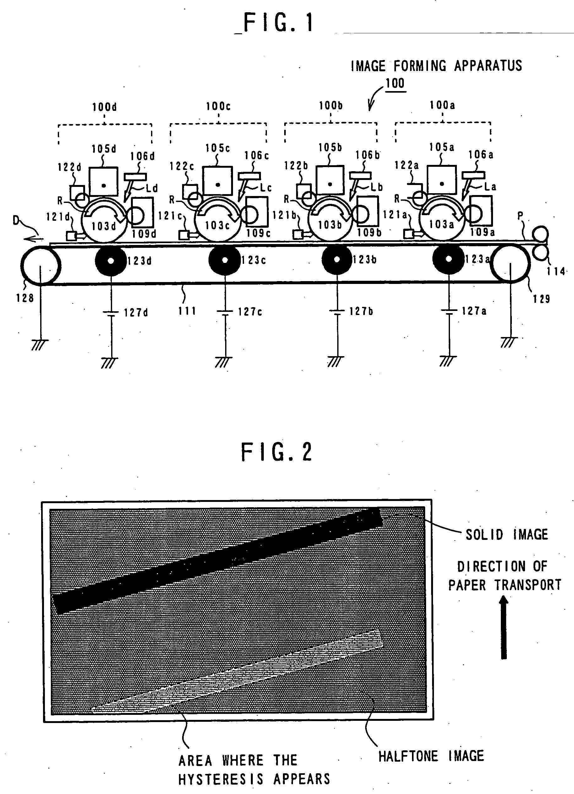
[0039] The image forming apparatus 100 having the above-mentioned configuration is used to form an image as follows. As the first example, an experiment is carried out to compare the conventional image forming method with the image forming method according to the present invention to change the irradiation intensity of a laser in the exposure apparatus with respect to an exposure error. Table 1 shows a result of visually evaluating the hysteresis of output images after developing the yellow, magenta, cyan, and black colors according to the conventional method. In the experiment, the four colors of toners are sequentially supplied to only the image forming unit 100d in order to eliminate an effect of the reverse transfer toner. Accordingly, the evaluation is carried out so that an image of each color can be formed under the same environmental condition. (In Table 1, numeral “4” represents a case most difficult to determine the hysteresis; numeral “1” represents a case easiest to dete...

example 2

[0043] As the second example, an experiment is carried out to compare the conventional image forming method with the image forming method according to the present invention to change the exposure resolution for a specific color. Table 3 shows a result that the untransferred black toner causes the image hysteresis depending on dots per inch. In this case, the method of collecting data follows that for Table 1. An exposure error due to untransferred toner causes the image hysteresis. As described in example 1, the image hysteresis is hardly recognizable on the solid image, but is recognizable on the halftone image containing an area where the development field is inconstant. It will be understood that the image hysteresis can be made inconspicuous by decreasing the exposure resolution for forming an electrostatic latent image compared to the other colors of toners especially with respect to an image forming portion greatly causing an exposure error such as the black toner.

TABLE 3Ima...

example 3

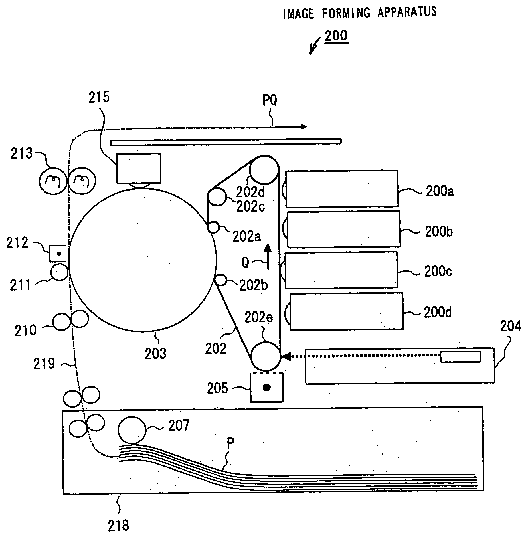
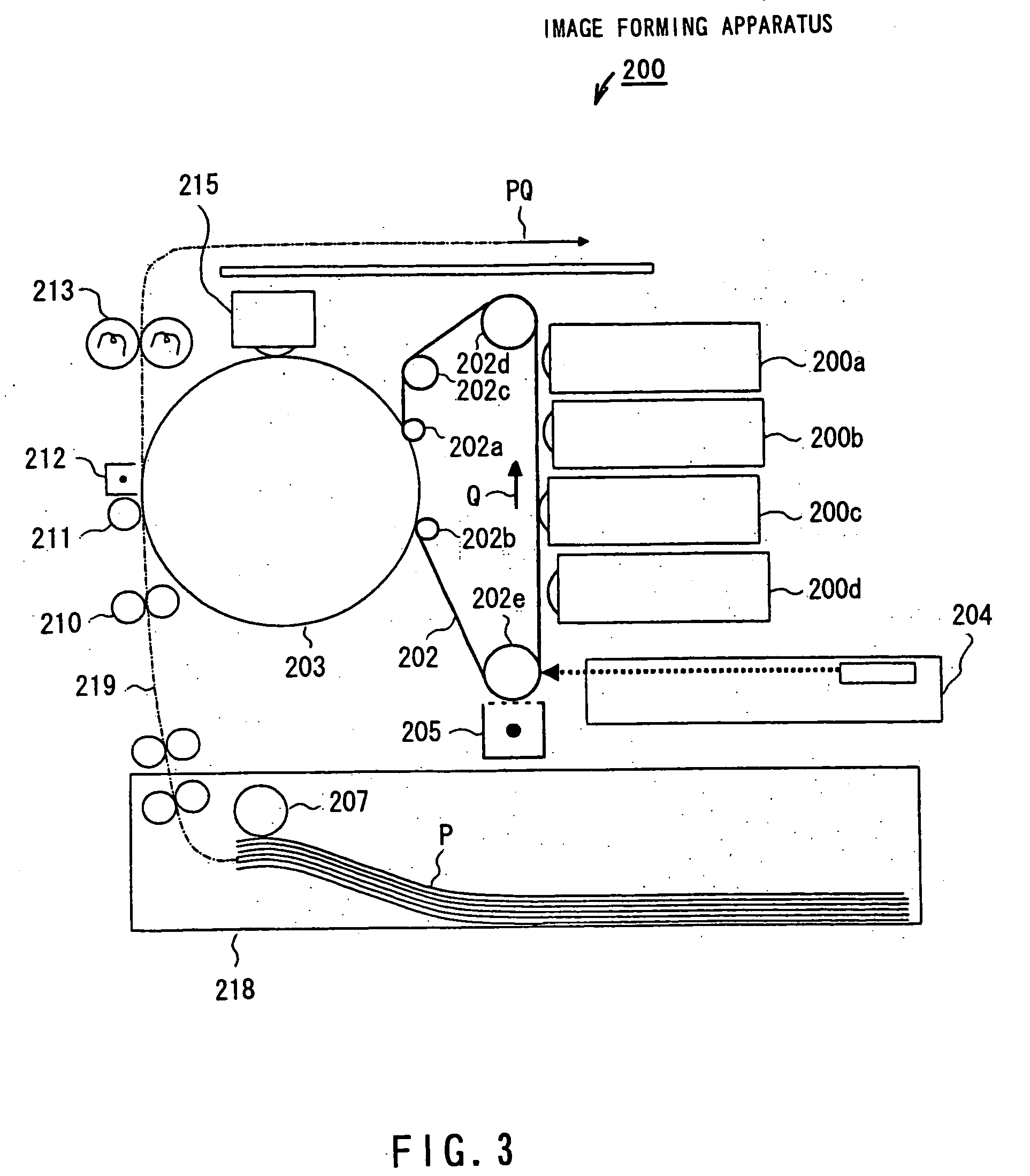
[0045] The following describes another example using an image forming apparatus 200 in FIG. 3 configured on the basis of the 4-rotation image forming system employing the photoreceptor cleanerless system. The configuration of the image forming apparatus 200 in FIG. 3 will be described first. The image forming apparatus 200 in FIG. 3 comprises a photoreceptor belt 202; rollers 202a, 202b, 202c, 202d, and 202e to hold and drive the photoreceptor belt 202; a charger 205; an exposure apparatus 204; four developing apparatuses 200a, 200b, 200c, and 200d; an intermediate transferrer 203; a paper cassette 218 with a sheet feed roller 207; a paper transport apparatus 219; an aligning roller 210; a transfer roller 211; a paper release apparatus 212; a fixing apparatus 213; and a intermediate transferrer cleaner 215.

[0046] In the image forming apparatus 200 of FIG. 3, the photoreceptor belt 202 is in close contact with the surface of the intermediate transferrer 203 by means of the rollers 2...


PUM


Abstract

There is provided a photoreceptor cleanerless image forming apparatus capable of decreasing color mixture or an exposure error due to reverse transfer toner or untransferred toner. An image forming apparatus 100 according to the present invention comprises four image forming units 100a, 100b, 100c, and 100d configured to be photoreceptor cleanerless in a 4-drum tandem manner. Each image forming unit includes a photoreceptor 103a, 103b, 103c, or 103d, a charger 105a, 105b, 105c, or 105d, an exposure apparatus 106a, 106b, 106c, or 106d, and a developing apparatus 109a, 109b, 109c, or 109d. When exposure intensities Iy, Ic, Im, and Ik are assumed for exposure sources of the exposure apparatuses in the image forming units which form yellow, magenta, cyan, and black images, respectively, the exposure intensities are configured to satisfy conditions of Ik≧Ic≧Im≧Iy and Ik>Iy. This decreases an exposure error (image hysteresis) in an image formed on paper.

Description

[0001] The present application is a divisional of U.S. application Ser. No. 10 / 385,716, filed Mar. 12, 2003, the entire contents of which are incorporated herein by reference.BACKGROUND OF THE INVENTION [0002] 1. Field of the Invention [0003] The present invention relates to an image forming apparatus and more particularly to a photoreceptor cleanerless image forming apparatus which overlappingly forms yellow, magenta, cyan, and black toner images and continuously prints color images. [0004] 2. Description of the Related Art [0005] The technology indicative of this type of image forming apparatus is disclosed in Jpn. Pat. Appln. Laid-Open Publication No. 5-341643, for example. While this example shows the photoreceptor cleanerless image forming apparatus handling a single color, it is developed to a 4-drum tandem image forming apparatus for continuously printing color images. FIG. 5 is a schematic diagram exemplifying a 4-drum tandem image forming apparatus according to the conventi...

Claims


Application Information

Patent Timeline
Patent Type & Authority Applications(United States)
IPC IPC(8): G03G15/01B41J2/385G03G15/041G03G21/00
CPCG03G15/0415G03G21/0064G03G2215/0119G03G2215/0164G03G15/0194G03G15/0115G03G15/0173G03G15/0189G03G2215/0602
Inventor AOKI, SHINJITAKAHASHI, MASASHIHIROKI, MASASHIWATANABE, TAKESHI
Owner KK TOSHIBA
Why Eureka
Try Eureka