Automatic document feeder and image forming apparatus including the same

a document feeder and image forming technology, applied in the direction of electrical devices, thin material processing, article separation, etc., can solve the problems of image forming itself becoming a load when the original, the image forming itself cannot be downsized contrary to the user's requirement, and the irregular speed of the feeder, etc., to achieve a compact size and minimize color shift

Inactive Publication Date: 2014-08-12
RICOH KK
View PDF14 Cites 2 Cited by
  • Summary
  • Abstract
  • Description
  • Claims
  • Application Information

AI Technical Summary

Benefits of technology

[0011]The present invention provides an automatic document feeder capable of minimizing color shift when reading an original image that is inexpensive, has a compact size, and an uncomplicated structure, and an image forming apparatus including such an optimal automatic document feeder. Specifically, an automatic document feeder includes: an upstream conveyance roller pair disposed upstream relative to an image reading line position of an image reader in a conveyance direction of an original, and including an upstream driving roller and an upstream driven roller; a downstream conveyance roller pair disposed downstream relative to an image reading line position of an image reader in the conveyance direction of an original, and including a downstream driving roller and a downstream driven roller; an upstream auxiliary roller pair including upstream auxiliary rollers disposed coaxially on a shaft of the upstream driving roller and of the upstream driven roller, respectively, each of the upstream auxiliary rollers formed of an elastic member and having a diameter greater than that of the adjacent upstream driving roller and of the adjacent upstream driven roller, respectively; and a downstream auxiliary roller pair including downstream auxiliary rollers disposed coaxially on a shaft of the downstream driving roller and of the downstream driven roller, respectively, each of the downstream auxiliary rollers formed of a low-hardness elastic member and having a diameter greater than that of the adjacent downstream driving roller and of the adjacent downstream driven roller, respectively.

Problems solved by technology

In addition, it is understood that such irregularity in speed occurs due to deformation of the conveyance materials such as the original or the conveyance roller pair when a drastic load change occurs with respect to the conveyed original.
However, when the roller diameter is increased, the automatic document feeder cannot be downsized and as a result, the image forming itself cannot be downsized contrary to the requirement of the users.
However, designing of the conveyance interval within such a range so as not to clog the original considering the thermal deformation and assembly errors is difficult, and further, a method to eliminate the conveyance path interval by using an elastic member such as mylar (registered trademark) has a problem in that the Mylar™ itself becomes a load when the original enters between rollers.
The above measure has a disadvantage in that, due to its importance to the structure of the automatic document feeder, the application of such a design is not allowed.
Another problem is that the roller pair comes to bite the reading device.
Another approach is to replace the reading white board mounted on the reading line with a belt or a roller, but doing so makes the device complicated and expensive.
However, the disclosed invention may not prevent fluctuations in the original conveyance speed when the original strikes between the roller pair and exits therefrom.

Method used


Image

  • Automatic document feeder and image forming apparatus including the same
  • Automatic document feeder and image forming apparatus including the same
  • Automatic document feeder and image forming apparatus including the same

Examples


Embodiment Construction

[0022]Hereinafter, preferred embodiments of the present invention will now be described with reference to the accompanying drawings.

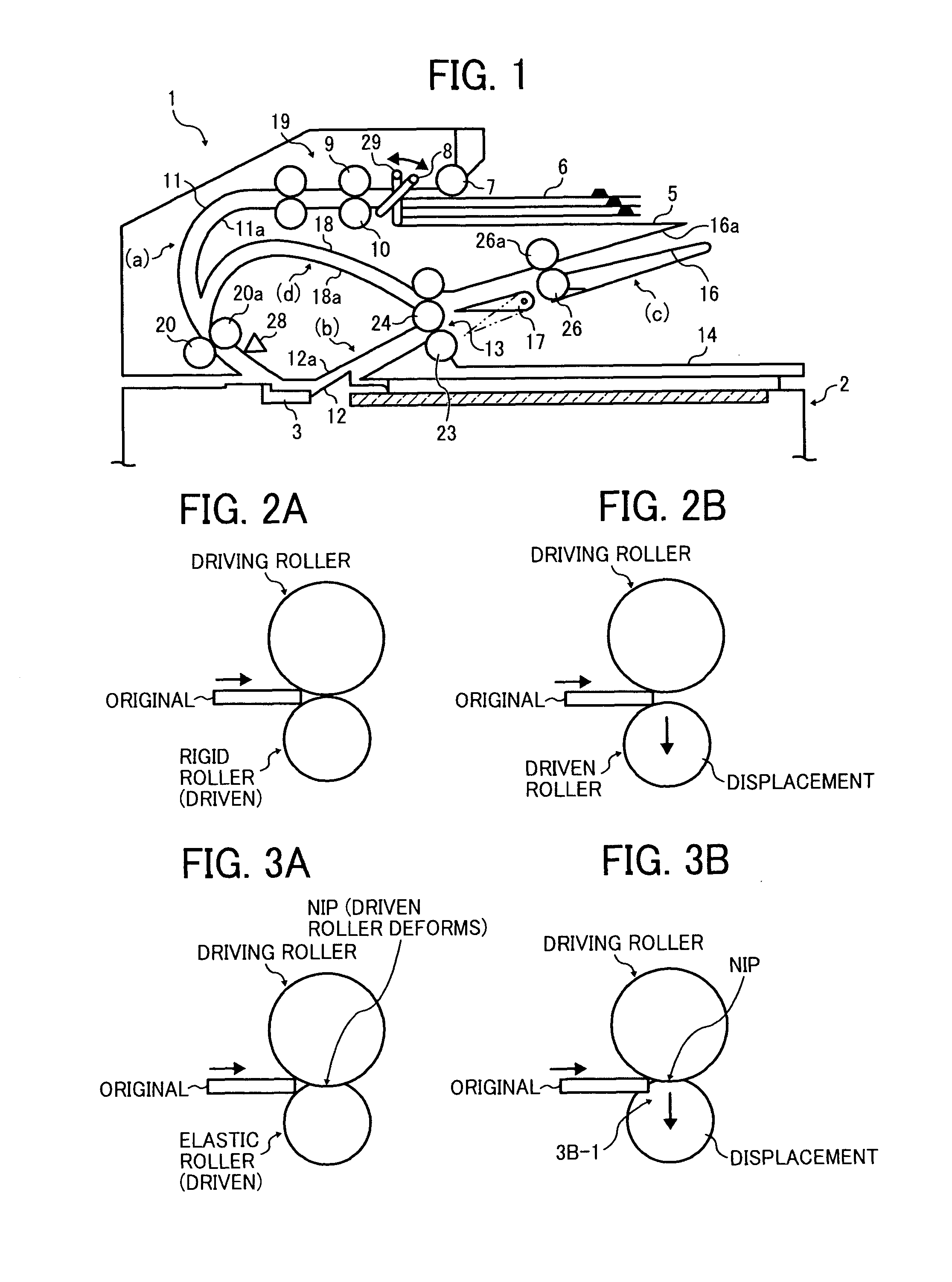
[0023]First, basic structure, operation, and effect of an automatic document feeder according to one embodiment of the present invention will be described with reference to FIG. 1. FIG. 1 shows a cross-sectional view of the automatic document feeder. This automatic document feeder can be mounted to, for example, a copier, a printer, a facsimile machine, and a multifunction apparatus including two or more.

[0024]As illustrated in FIG. 1, reference numeral 1 denotes an automatic document feeder which is openably disposed on and above an image reader or device 2 such as a scanner. The image reader 2 is provided with a slit glass 3 serving as a reading position on its surface thereof, which is a commonly known structure. When an original having images thereon passes through the linear image reading position below the slit glass 3, image information of the or...


PUM


Abstract

An automatic document feeder includes an upstream conveyance roller pair disposed upstream of an image reader including an upstream driving roller and an upstream driven roller; a downstream conveyance roller pair including a downstream driving roller and a downstream driven roller; an upstream auxiliary roller pair including upstream auxiliary rollers disposed coaxially on a shaft of the upstream driving roller and of the upstream driven roller, respectively, each formed of an elastic member and having a diameter greater than that of the adjacent upstream driving roller and of the adjacent upstream driven roller, respectively; and a downstream auxiliary roller pair including downstream auxiliary rollers each disposed coaxially on a shaft of the downstream driving roller and of the downstream driven roller, formed of a low-hardness elastic member and having a diameter greater than that of the adjacent downstream driving roller and of the adjacent downstream driven roller.

Description

CROSS-REFERENCE TO RELATED APPLICATIONS[0001]The present application claims priority from Japanese patent application number 2010-246190, filed on Nov. 2, 2010, the entire contents of which are incorporated by reference herein.FIELD OF THE INVENTION[0002]The present invention relates to an automatic document feeder incorporated in an image forming apparatus such as a printer, a copier, a facsimile machine, and a multi-function apparatus having one or more capabilities of the above devices, and to an image forming apparatus incorporating the automatic document feeder.BACKGROUND OF THE INVENTION[0003]In Optical Character Recognition (OCR) technology in which image information of an original such as a paper document is read by an image reader such as a scanner to create electronic data, an automatic document feeder is frequently used. In the automatic document feeder, each original is automatically extracted and separated from a bundle of originals sequentially one by one and is convey...

Claims


Application Information

Patent Timeline
Patent Type & Authority Patents(United States)
IPC IPC(8): B65H5/02B65H5/04
CPCB65H5/062B65H2404/143B65H2404/532B65H2404/563B65H2801/39H04N1/121H04N1/193B65H2220/09
Inventor HATAYAMA, KOJIYOUDA, YASUNOBUKUDOH, TAKUANDOH, TAKAYUKIOSANAI, YOHEINARAI, SATOSHIFUJII, TAKASHI
Owner RICOH KK
Why Eureka
Try Eureka