Electroluminescent display device

a technology of display device and electroluminescent light, applied in the direction of luminescent light screen, identification means, instruments, etc., can solve the problem of color purity dropping

Active Publication Date: 2006-06-13
SANYO ELECTRIC CO LTD
View PDF7 Cites 3 Cited by
  • Summary
  • Abstract
  • Description
  • Claims
  • Application Information

AI Technical Summary

Problems solved by technology

In this conventional EL device, light from the white organic EL

Method used


Image

  • Electroluminescent display device
  • Electroluminescent display device
  • Electroluminescent display device

Examples


Embodiment Construction

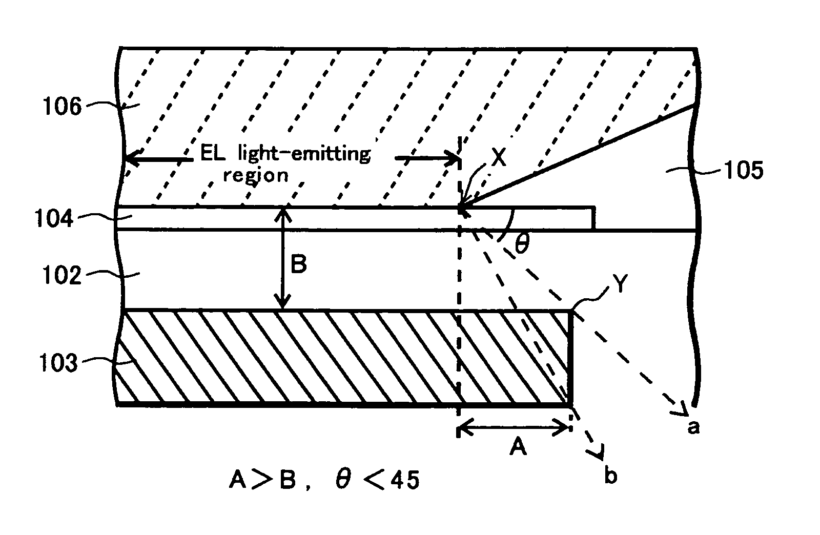
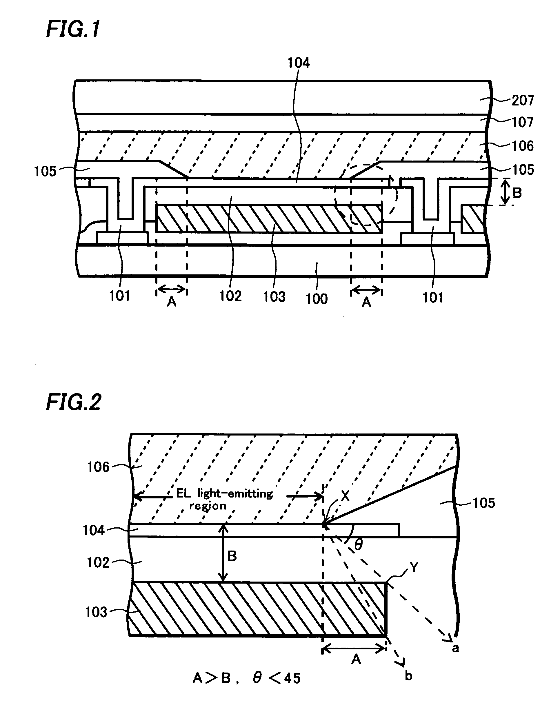
[0018]An embodiment of the invention will be described with reference to the drawings in detail. FIG. 1 is a schematic cross-sectional view showing a pixel of an organic EL display device of the embodiment. FIG. 2 is an enlarged view of a portion enclosed with a broken line in FIG. 1. In an actual organic EL display device, a plurality of the pixels is arranged in a matrix.

[0019]A numeral 100 designates a transparent insulating substrate such as a glass substrate, a numeral 101 designates an organic EL element driving TFT (thin film transistor) formed on the insulating substrate 100, and a numeral 102 designates a first planarization insulating film. A numeral 103 designates a color filter layer buried in the first planarization insulating film 102, a numeral 104 designates an anode layer made of ITO (indium tin oxide) which is connected with the TFT 101 and extends over the first planarization insulating film 102, and a numeral 105 designates a second planarization insulating film ...


PUM


Abstract

The invention provides an electroluminescent display device in which purity of R, G, and B colors is prevented from lowering by minimizing white light leakage and color mixture caused by an escape of light to an outside of a color filter layer. An organic EL element driving TFT is formed on an insulating substrate. A first planarization insulating film is formed so as to cover the organic EL element driving TFT. A color filter layer is buried in the first planarization insulating film. An anode layer is connected with the organic EL element driving TFT and extends over the first planarization insulating film. A second planarization insulating film is formed so as to cover end portions of the anode layer. Here, a length of an overlapping area of the color filter layer and the second planarization insulating film is set larger than a sum of thicknesses of the anode layer and the first planarization insulating film. Accordingly, most of light radiated from an organic EL layer can be transmitted through the color filter layer 103.

Description

BACKGROUND OF THE INVENTION[0001]1. Field of the Invention[0002]The invention relates to an electroluminescent display device, particularly to an electroluminescent display device having color filter layers.[0003]2. Description of the Related Art[0004]An organic electroluminescent (hereafter, referred to as EL) element is a self-emissive element. An organic EL display device using the organic EL elements is receiving an attention as a new display device substituted for a CRT or an LCD.[0005]FIG. 6 is a schematic cross-sectional view showing a pixel of a full-color organic EL display device of the conventional art. A numeral 200 designates a glass substrate, a numeral 201 designates an organic EL element driving TFT (thin film transistor) formed on the glass substrate 200, and a numeral 202 designates a first planarization insulating film. A numeral 203 designates an anode layer made of ITO (indium tin oxide) which is connected with the TFT 201 and extends over the first planarizatio...

Claims


Application Information

Patent Timeline
IPC IPC(8): H05B33/22G02B5/20G09F9/30G09G3/12H01L27/32H01L51/50H05B33/02H05B33/04H05B33/12H05B33/14
CPCH01L27/3246H01L27/322H10K59/38H10K59/122H05B33/22
Inventor NISHIKAWA, RYUJIMAEDA, KAZUYUKI
Owner SANYO ELECTRIC CO LTD
Why Eureka
Try Eureka