Cyclone dust collecting apparatus for vacuum cleaner

a vacuum cleaner and dust collection technology, applied in the field of vacuum cleaners, can solve the problems of increasing manufacturing costs, and achieve the effect of improving dust collection efficiency and increasing the swirling speed of air

Inactive Publication Date: 2005-03-31
SAMSUNG GWANGJU ELECTRONICS CO LTD
View PDF15 Cites 38 Cited by
  • Summary
  • Abstract
  • Description
  • Claims
  • Application Information

AI Technical Summary

Benefits of technology

[0008] Accordingly, it is an object of the present invention to provide a cyclone dust-collecting apparatus for a vacuum cleaner which is capable of increasing the swirling speed of air drawn in and swirled in a cyclone chamber, thereby improving the dust-collection efficiency.

Problems solved by technology

However, a vacuum generating source capable of generating a powerful suction force increases manufacturing costs.

Method used


Image

  • Cyclone dust collecting apparatus for vacuum cleaner
  • Cyclone dust collecting apparatus for vacuum cleaner
  • Cyclone dust collecting apparatus for vacuum cleaner

Examples


Embodiment Construction

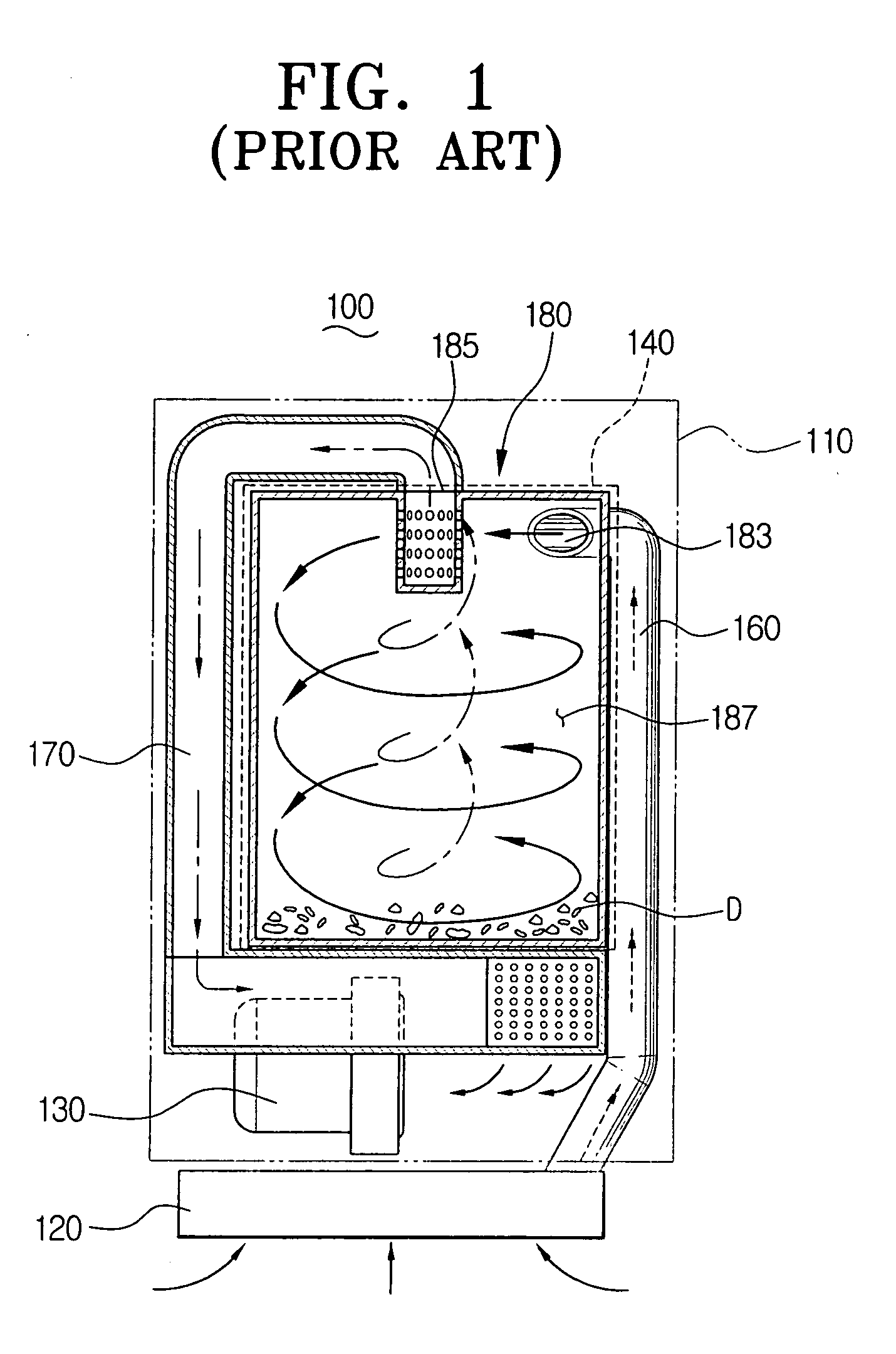
[0030] Exemplary embodiments of the present invention are described in detail below with reference to the accompanying drawings. In the following description of the embodiments of the present invention, like reference numerals are provided for elements having the same construction and function as the conventional vacuum cleaner with respect to FIG. 1 described above.

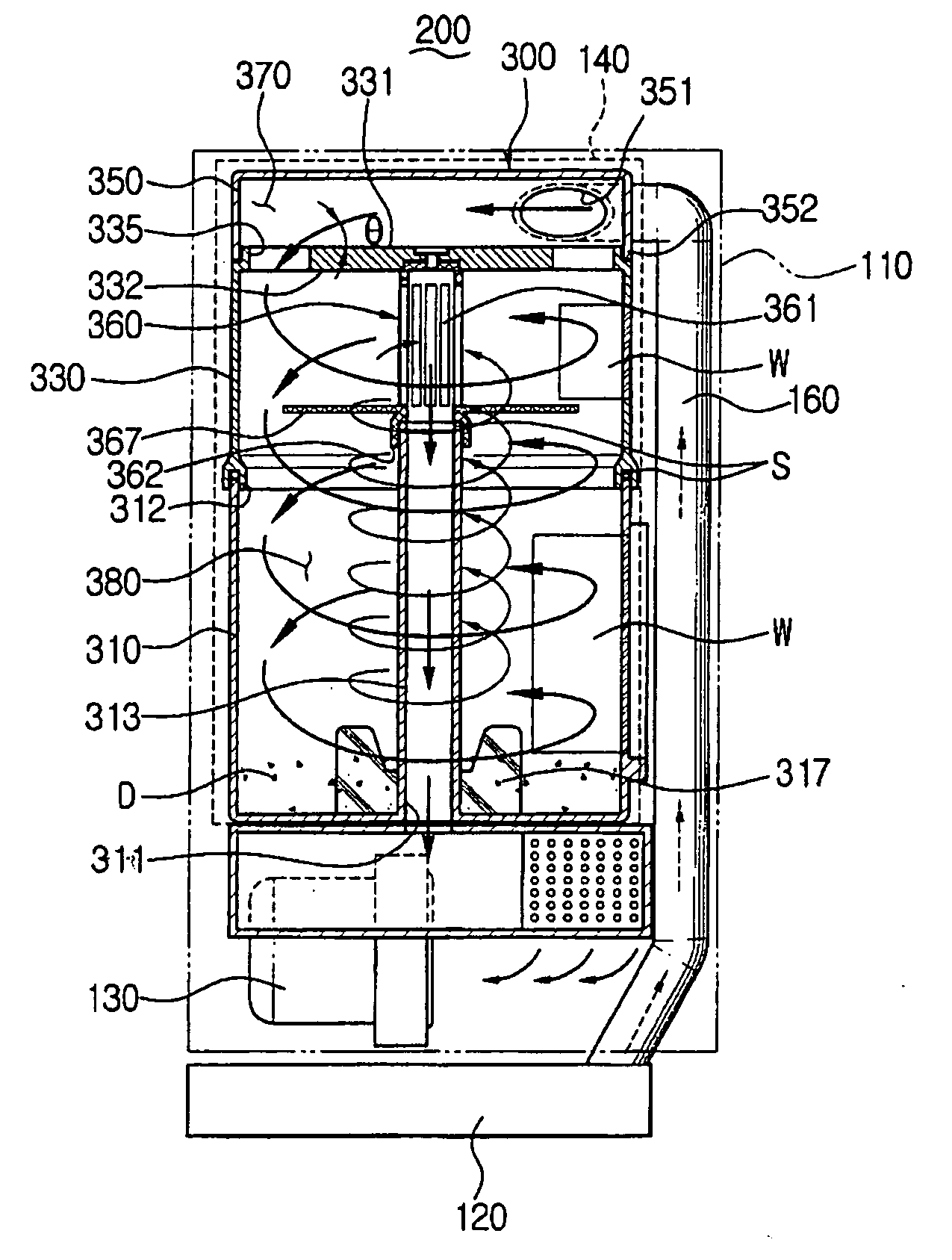
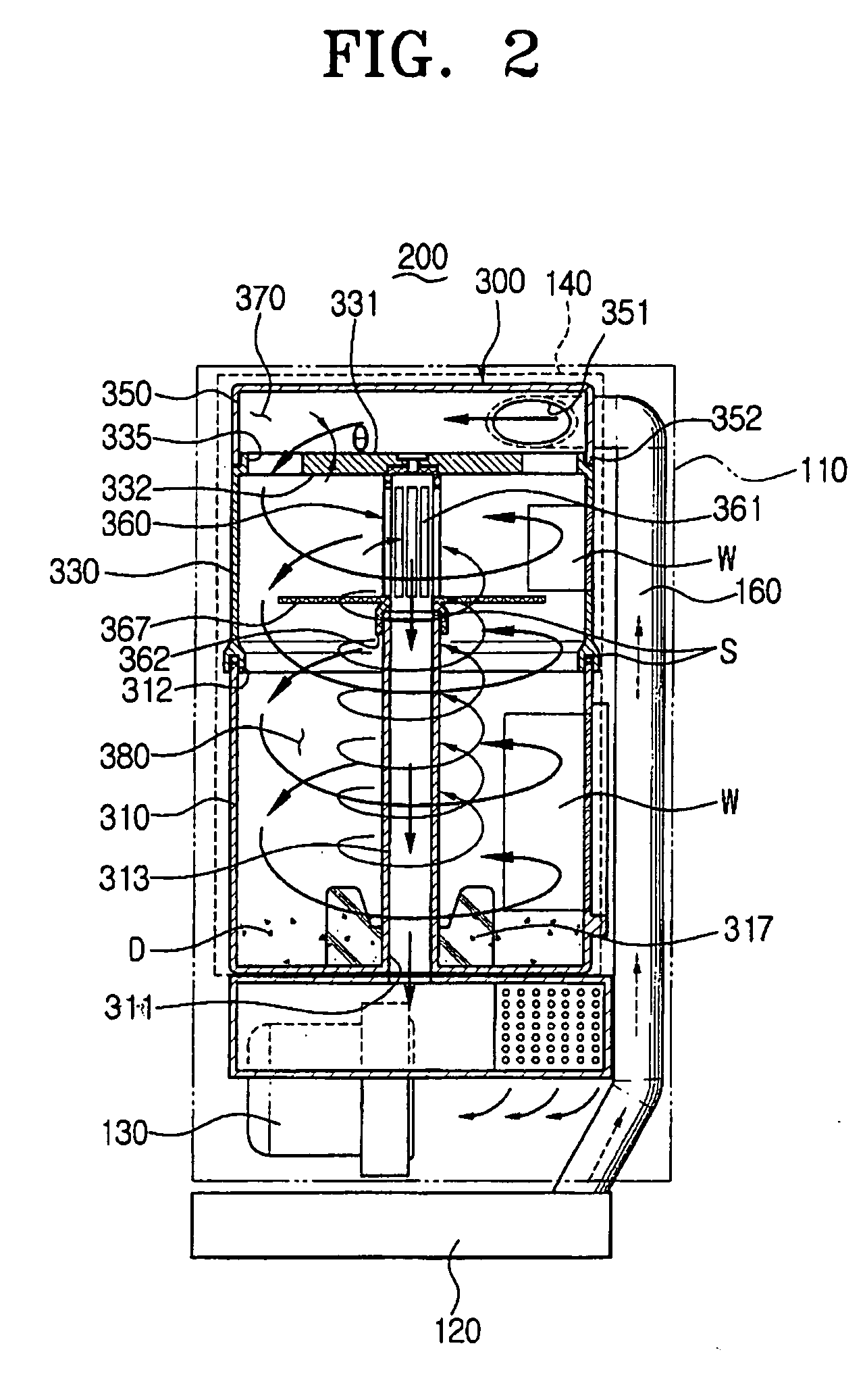
[0031] Referring to FIGS. 2 and 3, a cyclone dust-collecting apparatus 300 according to a first embodiment of the present invention includes a dirt-collecting receptacle 310, a first cover 330, and a second cover 350. The dirt-collecting receptacle 310, the first cover 330 and the second cover 350 are separably connected to one another and define a first chamber 370 and a second chamber 380 there between when connected together. The cyclone dust-collecting apparatus 300 is removably mounted in a dust-collecting chamber 140 of a cleaner body 110. The sealing members S prevent air leakage between respective connecting par...


PUM

PropertyMeasurementUnit
suction forceaaaaaaaaaa
angleaaaaaaaaaa
vacuumaaaaaaaaaa

Abstract

A cyclone dust-collecting apparatus comprises a first chamber fluidly communicated with a suction port, a second chamber fluidly communicated with the first chamber and a vacuum generating source, in which dirt is centrifugally separated form the air drawn in from the first chamber, and a partition having at least one penetrating hole connecting the first and the second chambers and at least one guide member disposed adjacent to the penetrating hole, the partition being formed between the first and the second chambers. Accordingly, when the air dispersed from the first chamber due to the penetrating hole and the guide member, flows into the second chamber, a speed of the swirling air in the second chamber increases. Therefore, the dust-collection efficiency of the cyclone dust collecting apparatus is improved.

Description

REFERENCE TO RELATED APPLICATION [0001] This application claims priority to copending Korean Patent Application No. 2003-67765, filed on Sep. 30, 2003, in the Korean Intellectual Property Office, which is incorporated herein by reference in its entirety. CROSS REFERENCE TO RELATED APPLICATIONS [0002] This application is related to copending applications entitled “Filter Cleaning Device of Cyclone Vacuum Cleaner” (Korean Application No. 2003-19951, filed Sep. 9, 2003), “Cyclone-Type Dust Collecting Apparatus for Vacuum Cleaner” (Korean Application No. 2002-0077811, filed Sep. 12, 2003), and “Cyclone Type Dust Collecting Apparatus for Vacuum Cleaner” (Korean Application No. 2003-33167, filed Oct. 10, 2003), and “Cyclone Dust Collecting Device And Vacuum Cleaner Having The Same” (Korean Application No. 2003-32152, filed Apr. 27, 2004) whose disclosures are commonly owned by the same assignee as the present application and are entirely incorporated herein by reference. FIELD OF THE INVE...

Claims


Application Information

Patent Timeline
Patent Type & Authority Applications(United States)
IPC IPC(8): A47L9/16B01D45/16B04C5/04B04C5/06B04C5/103B04C5/107B04C5/12B04C5/13
CPCA47L9/165A47L9/1666A47L9/1683B04C5/13B04C5/06B04C5/107B01D45/16A47L9/16
Inventor OH, JANG-KEUNLEE, HYUN-JU
Owner SAMSUNG GWANGJU ELECTRONICS CO LTD
Why Eureka
Try Eureka