Vehicle air conditioner with discharge capacity control of compressor

a technology of compressor and discharge capacity, which is applied in the direction of defrosting, lighting and heating equipment, domestic cooling equipment, etc., can solve the problems of insufficient recovery of deceleration energy and the inability to increase the discharge capacity of the compressor to the maximum capacity, and achieve the effect of recovering the deceleration energy of the vehicl

Active Publication Date: 2005-03-31
DENSO CORP
View PDF4 Cites 27 Cited by
  • Summary
  • Abstract
  • Description
  • Claims
  • Application Information

AI Technical Summary

Benefits of technology

[0007] In view of the above-described problems, it is an object of the present invention to provide a vehicle air conditioner, which sufficiently recovers deceleration energy of the vehicle.
[0008] It is another object of the present invention to provide a vehicle air conditioner, which prevents unpleasant feeling from being given to a passenger in a passenger compartment (compartment) while effectively recovers deceleration energy of the vehicle.
[0010] In the vehicle air conditioner, when the deceleration detecting unit detects the deceleration running state of the vehicle, the control unit controls the discharge capacity of the compressor approximately at a maximum capacity, regardless of the target cooling temperature. Specifically, in the deceleration running state of the vehicle, when the surface of the cooling heat exchanger is not dry, the discharge capacity of the compressor is controlled approximately to the maximum capacity. Therefore, the deceleration energy of the vehicle can be sufficiently recovered. In contrast, when the dry determination means determines that the surface of the cooling heat exchanger is dry, the control unit controls the discharge capacity of the compressor such that the temperature detected by the temperature detecting unit approaches the target cooling temperature, regardless of a detection result of the deceleration detecting unit. Accordingly, it can prevent unpleasant feeling from being given to a passenger in the compartment while the deceleration energy can be effectively recovered.
[0011] Alternatively, in the present invention, when the deceleration detecting unit detects the deceleration running state of the vehicle in a case where the dry determination means determines that the surface of the cooling heat exchanger is not dry, the control unit sets a corrected target cooling temperature that is lower than the target cooling temperature by a predetermined temperature. Furthermore, the control unit controls the discharge capacity of the compressor such that the temperature detected by the temperature detecting unit approaches the corrected target cooling temperature when the temperature detected by the temperature detecting unit is lower than the corrected target cooling temperature, or controls the discharge capacity of the compressor approximately at the maximum capacity regardless of the corrected target cooling temperature when the temperature detected by the temperature detecting unit is equal to or higher than the corrected target cooling temperature. Generally, when the temperature detected by the temperature detecting unit is lower than the corrected target cooling temperature, it is estimated that the cool storage can be largely used even when cold is further stored in the cooling heat exchanger. In contrast, when the temperature detected by the temperature detecting unit is equal to or higher than the corrected target cooling temperature, because the discharge capacity of the compressor is controlled to an approximate maximum capacity regardless of the corrected target cooling temperature, the cool storage of the cooling heat exchanger can be effectively performed during the deceleration running state of the vehicle.

Problems solved by technology

Accordingly, when the vehicle deceleration is finished, the discharge capacity of the compressor may be not increased to the maximum capacity, and the deceleration energy cannot be recovered sufficiently.

Method used


Image

  • Vehicle air conditioner with discharge capacity control of compressor
  • Vehicle air conditioner with discharge capacity control of compressor
  • Vehicle air conditioner with discharge capacity control of compressor

Examples


Embodiment Construction

[0018] A preferred embodiment of the present invention will be described hereinafter with reference to the appended drawings.

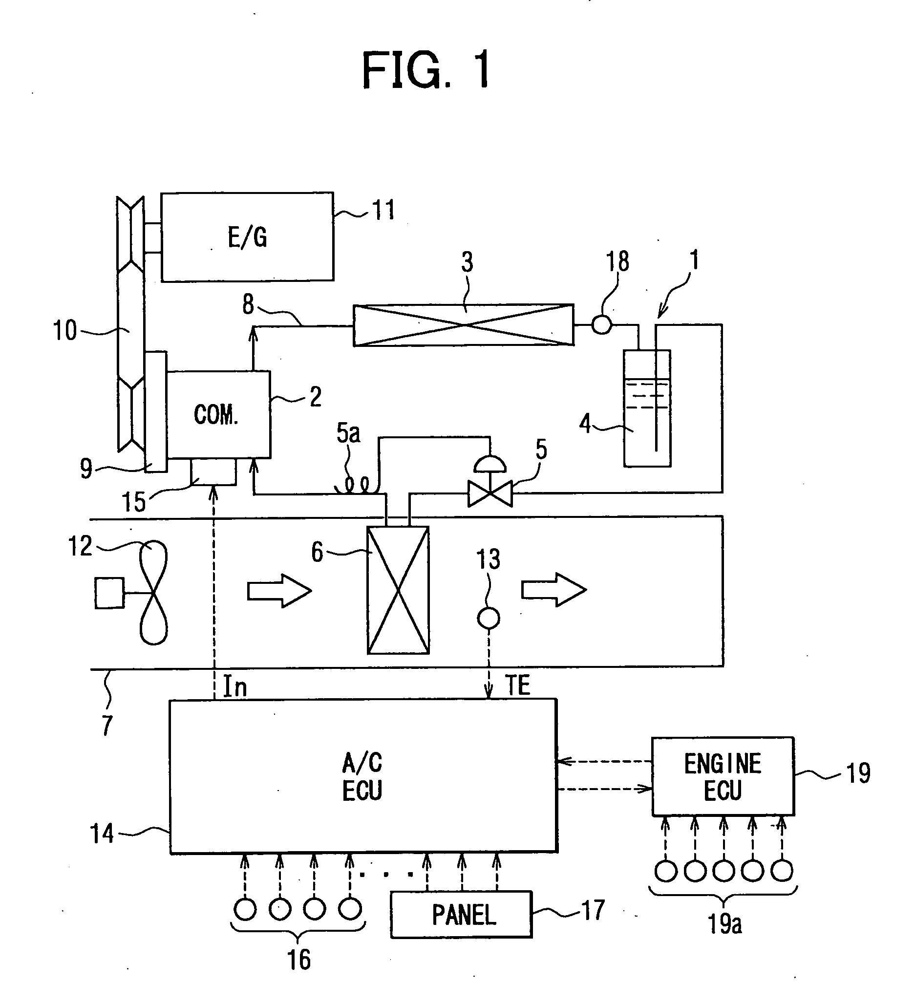
[0019] As shown in FIG. 1, a refrigerant cycle device 1 of a vehicle air conditioner includes a compressor 2, a condenser 3, a receiver 4 (gas-liquid separator), an expansion valve 5 (decompression device) and an evaporator 6. The compressor 2 sucks, compresses and discharges refrigerant in the refrigerant cycle device 1. Super-heating gas refrigerant having high-temperature and high-pressure is discharged from the compressor 2, and flows into the condenser 3. In the condenser 3, refrigerant is heat-exchanged with outside air blown by a cooling fan to be cooled and condensed.

[0020] The refrigerant cooled and condensed in the condenser 3 flows into the receiver 4, and is separated into gas refrigerant and liquid refrigerant in the receiver 4. Generally, surplus refrigerant in the refrigerant cycle device 1 is stored in the receiver 4 as liquid refrigerant. Li...


PUM


Abstract

In a vehicle air conditioner having a variable displacement compressor, a control unit calculates a target cooling temperature of air to be cooled by an evaporator, and controls a discharge capacity of the compressor such that a detected air temperature of the evaporator approaches the target cooling temperature. When a deceleration running state of the vehicle is detected, the control unit sets a corrected target cooling temperature lower than the target cooling temperature by a predetermined temperature, and controls the discharge capacity of the compressor such that the detected air temperature approaches the corrected target cooling temperature when the detected air temperature is lower than the corrected target cooling temperature, or controls the discharge capacity of the compressor approximately at the maximum capacity regardless of the corrected target cooling temperature when the detected air temperature is not lower than the corrected target cooling temperature.

Description

CROSS-REFERENCE TO RELATED APPLICATION [0001] This application is related to and claims priority from Japanese Patent Application No. 2003-340332 filed on Sep. 30, 2003, the content of which is hereby incorporated by reference. BACKGROUND OF THE INVENTION [0002] 1. Field of the Invention [0003] The present invention relates to a vehicle air conditioner with a discharge capacity control of a compressor. The vehicle air conditioner performs a cool storage in a cooling heat exchanger during a vehicle deceleration to recover deceleration energy of the vehicle. [0004] 2. Description of Related Art [0005] In a conventional vehicle air conditioner, a temperature of air cooled by an evaporator is detected by a temperature sensor, and a driving control of a compressor is performed so that a detected temperature of the temperature sensor becomes a target cooling temperature (e.g., JP-A-57-44511, JP-A-2001-105846). Furthermore, during a vehicle deceleration, the target cooling temperature is d...

Claims


Application Information

Patent Timeline
Patent Type & Authority Applications(United States)
IPC IPC(8): B60H1/32
CPCB60H1/3205B60H1/3208B60H2001/3261F25B2600/023B60H2001/327B60H2001/3275B60H2001/3266
Inventor SUGESAWA, NAOSHIWAKISAKA, TAKESHINAKAGAWA, TADASHITAKAGI, NOBORU
Owner DENSO CORP
Why Eureka
Try Eureka