Data conversion method and apparatus, and orientation measurement apparatus

a data conversion and orientation measurement technology, applied in the direction of instruments, television systems, static indicating devices, etc., can solve the problems of limited degree of freedom in application design, difficult to apply this method to an existing application, and the inability to freely design reference coordinate systems. to achieve the effect of facilitating the re-derivation of alignment data

Active Publication Date: 2005-03-31
CANON KK
View PDF5 Cites 38 Cited by
  • Summary
  • Abstract
  • Description
  • Claims
  • Application Information

AI Technical Summary

Benefits of technology

[0039] The present invention has been made in consideration of the above problems, and has as its object to allow easy re-derivation of alignment data without placing any restriction on design of a reference coordinate system.

Problems solved by technology

If intrinsic parameters of the image sensing device are known, a problem of registration in mixed reality eventuates in a problem of calculating extrinsic parameters of the image sensing device, i.e., the position and orientation of the image sensing device on a reference coordinate system set on the physical space.
However, this method suffers a program that the reference coordinate system cannot be freely designed.
For this reason, the degree of freedom in design of an application is limited.
Also, it is difficult to apply this method to an existing application which has a unique reference coordinate system.

Method used


Image

  • Data conversion method and apparatus, and orientation measurement apparatus
  • Data conversion method and apparatus, and orientation measurement apparatus
  • Data conversion method and apparatus, and orientation measurement apparatus

Examples


first embodiment

[0057] [First Embodiment]

[0058] This embodiment will explain a case wherein the orientation measurement method of the present invention is applied to an image display apparatus that presents mixed reality.

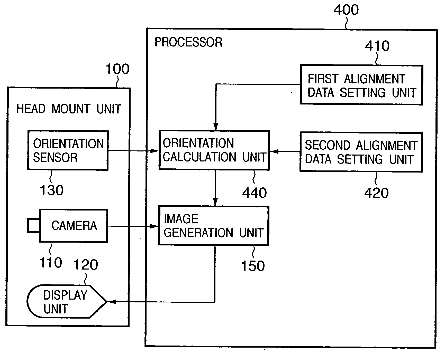
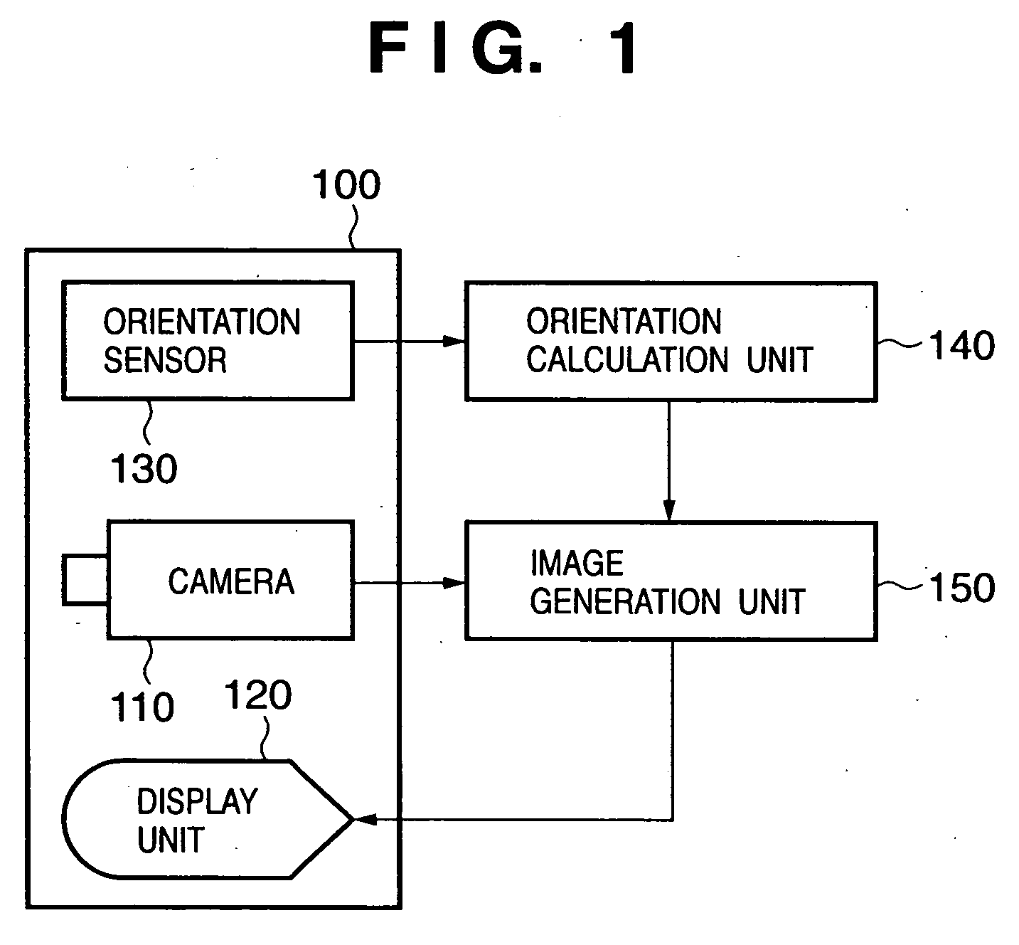
[0059]FIG. 4 shows the apparatus arrangement of an image display apparatus in this embodiment. As shown in FIG. 4, the image display apparatus of this embodiment adopts an arrangement having an orientation calculation unit 440 as a building component corresponding to the orientation calculation unit 140 in the image display apparatus shown in FIG. 1. First and second alignment data setting units 410 and 420 are added as building components. Note that the operations of the head-mount unit 100, camera 110, display unit 120, orientation sensor 130, and image generation unit 150 are the same as those in the image display apparatus shown in FIG. 1, and a description thereof will be omitted. In this embodiment, an arrangement other than the head-mount unit 100 will be handled as a proce...

second embodiment

[0090] [Second Embodiment]

[0091] The first embodiment has explained a case wherein an orientation sensor such as TISS-5-40 or InertiaCube2 which as the gravitational direction as the Z-axis is used. However, the scope of the present invention is no limited to the arrangement using such specific sensor. The orientation measurement method of the present invention can be applied to any other sensors as long as an orientation sensor has a sensor coordinate system which is set in association with the gravitational direction.

[0092] This embodiment will explain a case wherein the orientation measurement method of the present invention is applied to an image display apparatus that presents mixed reality and comprises an orientation sensor which is designed to have the gravitational direction as an axis other than the Z-axis.

[0093]FIG. 7 shows the apparatus arrangement of an image display apparatus in this embodiment. As shown in FIG. 7, the image display apparatus of this embodiment adopt...

third embodiment

[0104] [Third Embodiment]

[0105] In the above embodiments, the orientation measurement apparatus and method of the present invention are applied to the image display apparatus that presents mixed reality. However, the orientation measurement apparatus and method of the present invention can be used in various other applications that measure the orientation of an object using an orientation sensor.

[0106]FIG. 9 shows an example of the apparatus arrangement of an orientation measurement apparatus according to this embodiment. As shown in FIG. 9, the orientation measurement apparatus of this embodiment comprises a computer 900 and orientation sensor 130, which latter is the same as that in the first embodiment.

[0107] The orientation sensor 130 is fixed to an arbitrary object 910 to be measured.

[0108] The computer 900 has an orientation calculation unit 940 as a building component corresponding to the orientation calculation unit 440 in the first embodiment. Also, the computer 900 has ...


PUM


Abstract

An orientation sensor (130) measures the orientation of the orientation sensor (130) itself on a sensor coordinate system, and outputs an orientation measurement value. A first alignment data setting unit (410) reads out first alignment data, which is recorded in an external storage device (not shown) and represents the gravitational direction on a reference coordinate system, and sets that data in an orientation calculation unit (940). A second alignment data setting unit (420) sets second alignment data, which represents a difference angle in the azimuth direction between the sensor coordinate system and reference coordinate system in the orientation calculation unit (940) in accordance with a command input by an operator from a command input unit (not shown). The orientation calculation unit (940) calculates the orientation of an object on the reference coordinate system using the first and second alignment data on the basis of the orientation measurement value input from the orientation sensor (130), and outputs it. When the orientation of an object on an arbitrary set reference coordinate system is to be measured using the orientation sensor, alignment data required to make conversion from the sensor coordinate system into the reference coordinate system can be easily set.

Description

FIELD OF THE INVENTION [0001] The present invention relates to a technique for measuring the orientation of an object using an orientation sensor. BACKGROUND OF THE INVENTION [0002] In recent years, studies about mixed reality (MR) that aims at seamless joint of physical and virtual spaces have been extensively made. An image display apparatus which presents mixed reality is implemented by an apparatus which superimposes an image of a virtual space (e.g., a virtual object, text information, and the like rendered by computer graphics) onto an image of a physical space captured by an image sensing device such as a video camera or the like. [0003] As applications of such image display apparatus, navigation that superimposes the names and information of famous buildings and the like as virtual space images in an image of a physical space obtained by capturing an urban area, a landscape simulation that superimposes a computer graphics image of a building which is planned to be constructe...

Claims


Application Information

Patent Timeline
Patent Type & Authority Applications(United States)
IPC IPC(8): G01C9/00G01C21/20G06F3/00G06F3/01G09G5/00G09G5/36G09G5/377H04N5/262
CPCG01C9/00G06F3/012G01C21/20
Inventor SATOH, KIYOHIDEANABUKI, MAHORO
Owner CANON KK
Why Eureka
Try Eureka