Embossing apparatus

a technology of embossing apparatus and embossing surface, which is applied in the field of embossing methods and materials, can solve the problems of limited thickness of coating, limited ability to separate burn embossing, and limited application of the above-described methods

Inactive Publication Date: 2005-03-31
VAUGHN JEFFREY MOSS +1
View PDF32 Cites 2 Cited by
  • Summary
  • Abstract
  • Description
  • Claims
  • Application Information

AI Technical Summary

Problems solved by technology

However, when the embossing patterns need be “unmatched,” (i.e., when the shape and dimensions of the protrusions of a first engraved roll are substantially not identical with that of the corresponding recessions of the second engraved roll, although the corresponding protrusions and recessions are still positioned in registry relative to each other such that they engage) the above described methods can become limited to situations wherein the unmatched parameters are relatively small.
The limitation is due to the limited thickness of the coating that can be applied to coat the elements of the embossing pattern without deforming the desired shape of the protrusions and recessions, for example, by rounding the sharp edges of the embossing elements and the like.
Unfortunately, the practicalities of laser burning limit the ability to separately burn the embossing patterns of a pair of rolls that would, when brought into engagement with each other, engage uniformly over a substantially entire area of the embossing patterns.
However, such problems often cannot be tolerated when “a substantial number” of uniform engagements is still not sufficient to produce a desired product.
For example, when a desired sidewall clearance between the inter-engaged protrusions and recessions of the embossing rolls is not uniform throughout the entire area of the embossing rolls and there are points of engagement having insufficient clearance in order to separate the sidewall of the inter-engaged protrusions and recessions, the points of insufficient clearance can result in material production defects such as pinholes, nips, and other undesired deformities the embossed web material, which can be unacceptable in such web material products as, for example, a storage wrap material that can be used for wrapping food products and can tolerate none or only a limited number of pinholes, in order to efficiently protect the food product or any other product requiring protection from ambient environment.
However, in addition to the limitation in the range of the sidewall clearance that can be used in the above method, such resilient materials are often prone to accelerated wear, and can result in undesirable production downtime, which is required to remove the worn roll and to install a new roll.

Method used


Image

  • Embossing apparatus
  • Embossing apparatus
  • Embossing apparatus

Examples


example

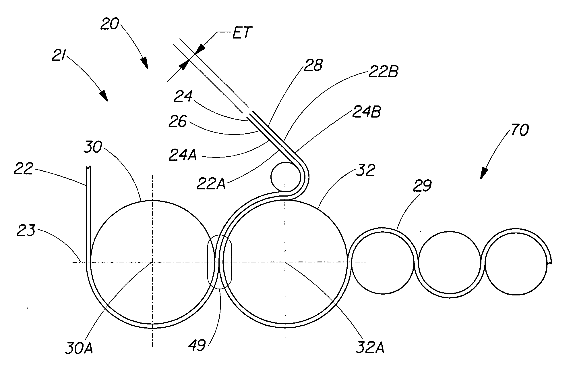
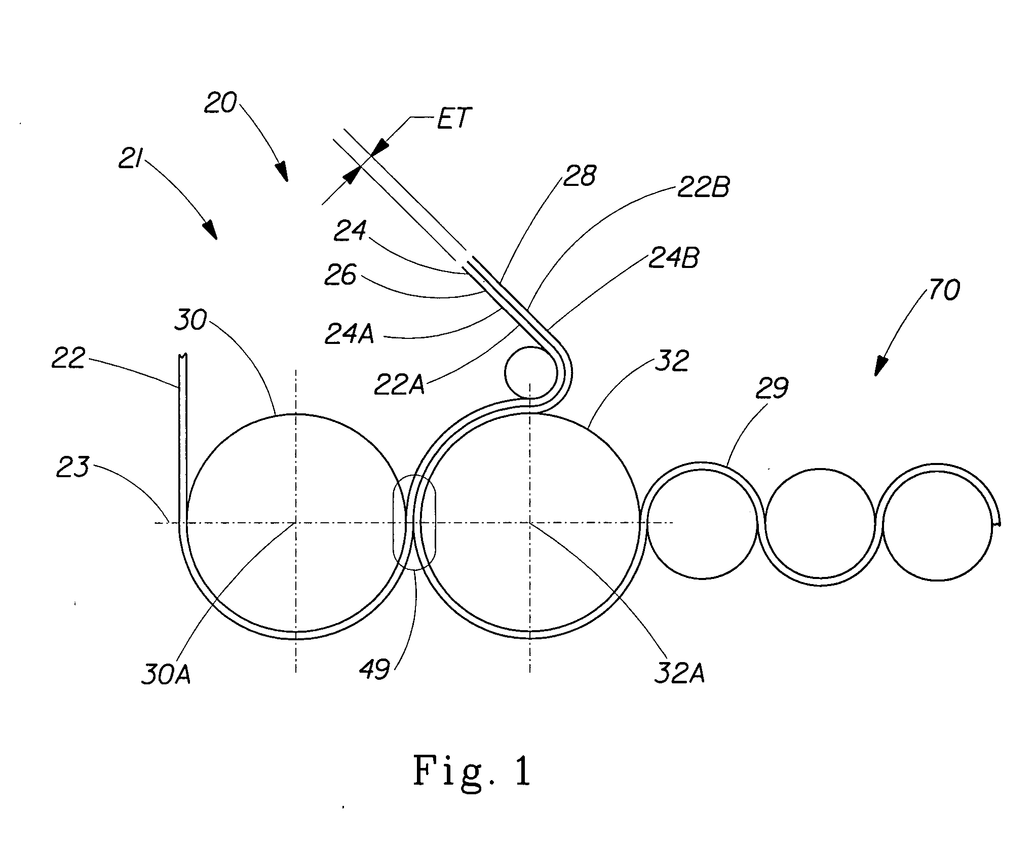
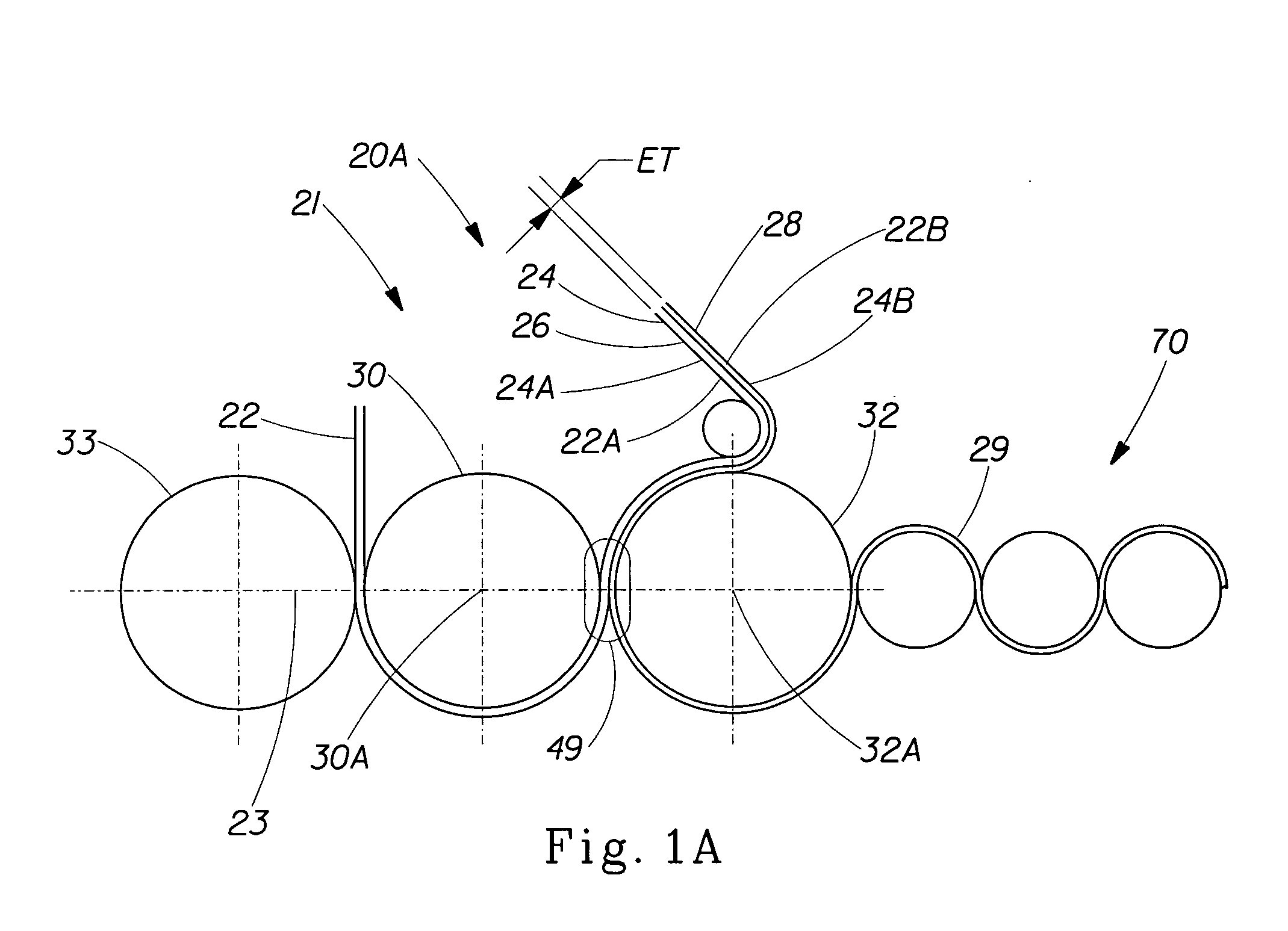
[0049] This example provides an exemplary method of providing one embodiment of the apparatus of the present invention for producing one embodiment of an embossed web material of the present invention such as a wrap material for wrapping a food product. The wrap material of the present invention must have preferably no pinholes or at least not more than about 12 pinholes per a material product size of about 72 square inches, in order to provide an effective protection of the wrapped food product.

[0050] The wrap material of the present invention was formed from a relatively thin deformable film, and, thus can require a relatively small sidewall clearance—usually from about 0.002″ (about 0.050 mm) to about 0.008″ (about 0.203 mm)—between the unmatched embossing patterns of the embossing rolls forming the embossed web. However, it should be noted that the present example is intended to also represent other instances where the embossed material can be relatively thick, including films ...


PUM

PropertyMeasurementUnit
radial depthaaaaaaaaaa
widthaaaaaaaaaa

Abstract

Disclosed is an embossing method and material made by the method, including at least a pair of embossing rolls having unmatched embossing patterns engraved independently from each other, and having enlarged sidewall clearances between adjacent, inter-engaged protrusions and recessions of the embossing patterns. The sidewall clearances can range from about 0.002″ (about 0.050 mm) to about 0.050″ (about 1.27 mm). The width of the protrusions can be greater than about 0.002″ or about 0.050 mm. The peripheral surface of at least one of the embossing rolls can comprise a metal, a plastic, a ceramic, or a rubber. Also disclosed is an embossed web material capable of being used as a wrap material for food products, made by the above process.

Description

CROSS-REFERENCE TO RELATED APPLICATION [0001] This application is a divisional of Ser. No. 10 / 165,475, filed Jun. 7, 2002.FIELD OF THE INVENTION [0002] The present invention relates to embossing methods and materials. Particularly, to embossing methods and materials produced by at least a pair of inter-engaged embossing rolls having unmatched embossing patterns separated from each other by a substantially large sidewall clearance. BACKGROUND OF THE INVENTION [0003] Many embossed web or sheet-type materials can be fabricated by a pair of embossing rolls, wherein each roll has an embossing pattern engraved on the peripheral surface of the roll. The rolls are inter-engaged with each other via their respective embossing patterns at a certain radial depth of engagement. The inter-engaged rolls rotate in opposite directions and impart embossing patterns on both sides of a deformable web or sheet-type material passing between the rotating embossing rolls. The web or sheet-type material bec...

Claims


Application Information

Patent Timeline
Patent Type & Authority Applications(United States)
IPC IPC(8): B31F1/07
CPCB31F1/07B31F2201/072B31F2201/0728B31F2201/0733Y10T428/24479B31F2201/0748B31F2201/0779B31F2201/0787B31F2201/0738
Inventor VAUGHN, JEFFREY MOSSMCNEIL, KEVIN B.
Owner VAUGHN JEFFREY MOSS
Why Eureka
Try Eureka