Annular one-way valve
a one-way valve, annular technology, applied in the direction of functional valve types, pliable tubular containers, containers, etc., can solve the problems of additional “dripping” flow, valves are relatively complex, and remaining fluid can also contaminate the valv
- Summary
- Abstract
- Description
- Claims
- Application Information
AI Technical Summary
Benefits of technology
Problems solved by technology
Method used
Image
Examples
Embodiment Construction
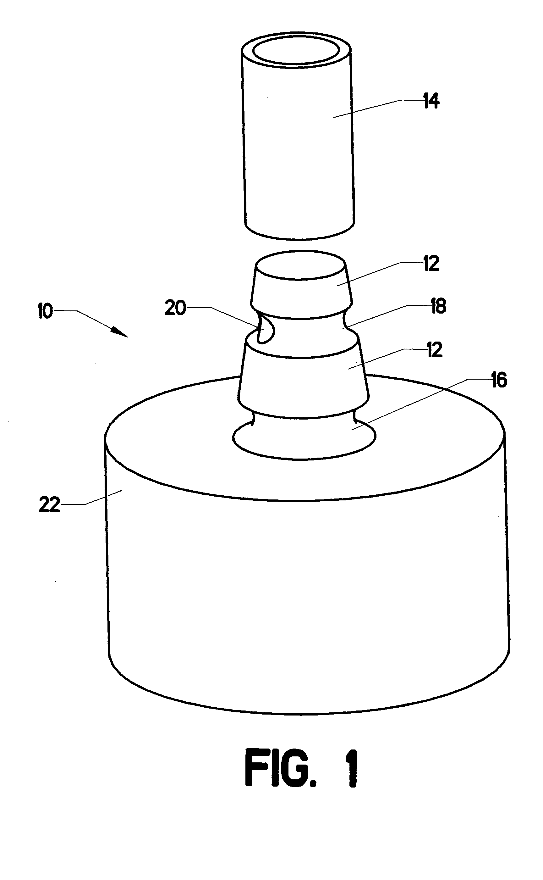
[0016]FIG. 1 shows valve assembly 10 in a disassembled state. Truncated cone 12 has a lower end that is larger then its upper end (where “upper” and “lower” are understood in the context of the orientation shown in the view). Retaining groove 16 is cut into the lower end, while fluid groove 18 is cut into the truncated cone between retaining groove 16 and the upper end of the truncated cone. Connector 22 provides a connection point to a source of fluid which feeds into the valve. Elastic cylinder 14 is hollow. It is made of a pliable material, so that it can be slipped over truncated cone 12, as will be described subsequently.
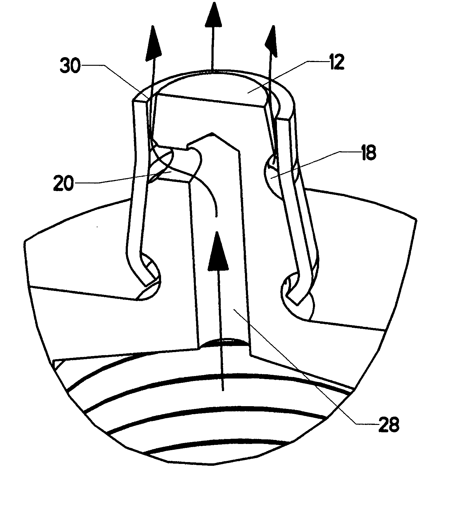
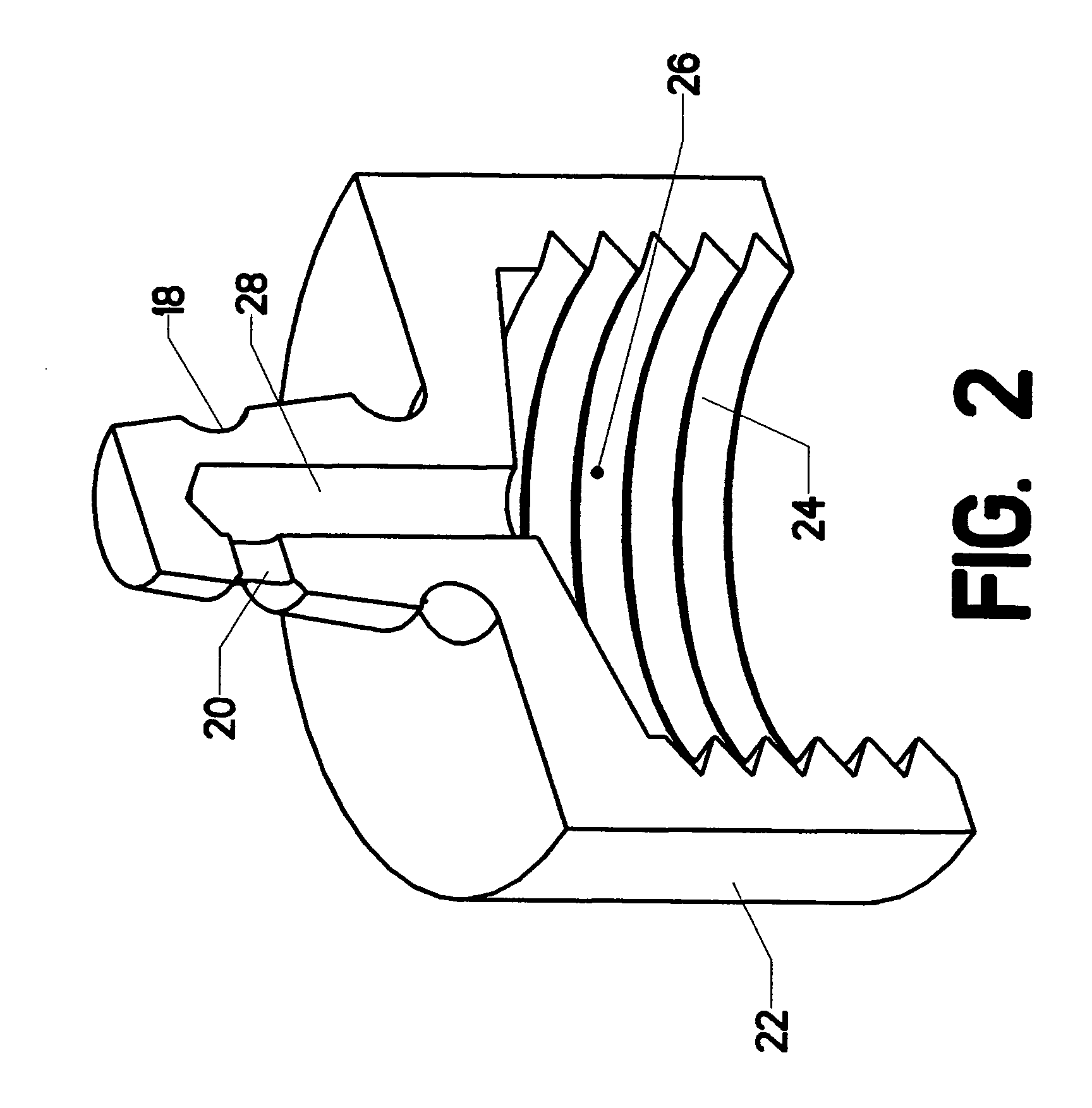
[0017]FIG. 2 is a sectional view through the valve, with elastic cylinder 14 removed. Fluid flows fron inside connector 22 through inlet cavity 26, fluid manifold 28, and conduit 20. Conduit 20 connects fluid manifold 28 to fluid groove 18.
[0018]FIG. 3 shows a view of valve assembly 10 in an assembled state. Elastic cylinder 14 has been placed over truncated ...
PUM
 Abstract
Description
Claims
Application Information
 - R&D
- Intellectual Property
- Life Sciences
- Materials
- Tech Scout
- Unparalleled Data Quality
- Higher Quality Content
- 60% Fewer Hallucinations
Browse by: Latest US Patents, China's latest patents, Technical Efficacy Thesaurus, Application Domain, Technology Topic, Popular Technical Reports.
© 2025 PatSnap. All rights reserved.Legal|Privacy policy|Modern Slavery Act Transparency Statement|Sitemap|About US| Contact US: help@patsnap.com


