
Surgical clamp

a surgical and clamping technology, applied in the field of surgical clamps, can solve the problems of additional difficulty in clamping, positioning the clamp, and securing the retractor support apparatus with the clamp, and reducing the safety of the patien

Inactive Publication Date: 2005-04-14
MINNESOTA SCI
View PDF19 Cites 23 Cited by
  • Summary
  • Abstract
  • Description
  • Claims
  • Application Information

AI Technical Summary

Problems solved by technology

However, the retractor support apparatus can be burdensome and difficult to position.
Additionally, the clamp is typically free to move along the length of the field post which creates additional difficulty in securing the retractor support apparatus with the clamp.
Therefore, securing the retractor support apparatus with a clamp and positioning the clamp in a selected position on the field post can pose difficulties.
The design of the clamp can also add to the difficulty in mounting the retractor support apparatus to the field post.
However, the weight and configuration of the retractor support apparatus may create potential difficulties in positioning the end of the retractor support apparatus within the clamping bore.

Method used


Image

  • Surgical clamp
  • Surgical clamp
  • Surgical clamp

Examples


Embodiment Construction

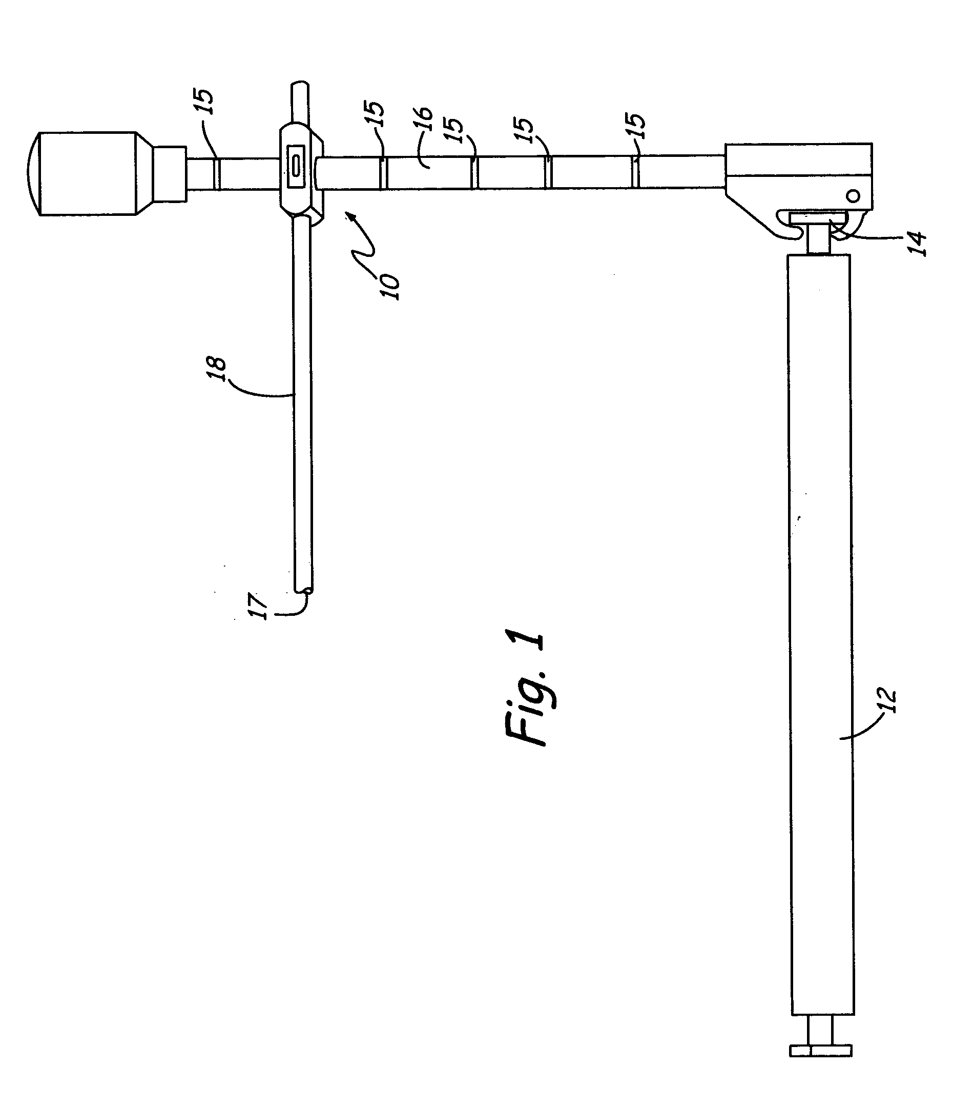
[0020] The present invention includes a surgical clamp illustrated in FIG. 1 at 10. The surgical clamp 10 secures a retractor support apparatus 18 to a field post 16 where the field post 16 is mounted to a rail 14 of a surgical table 12.

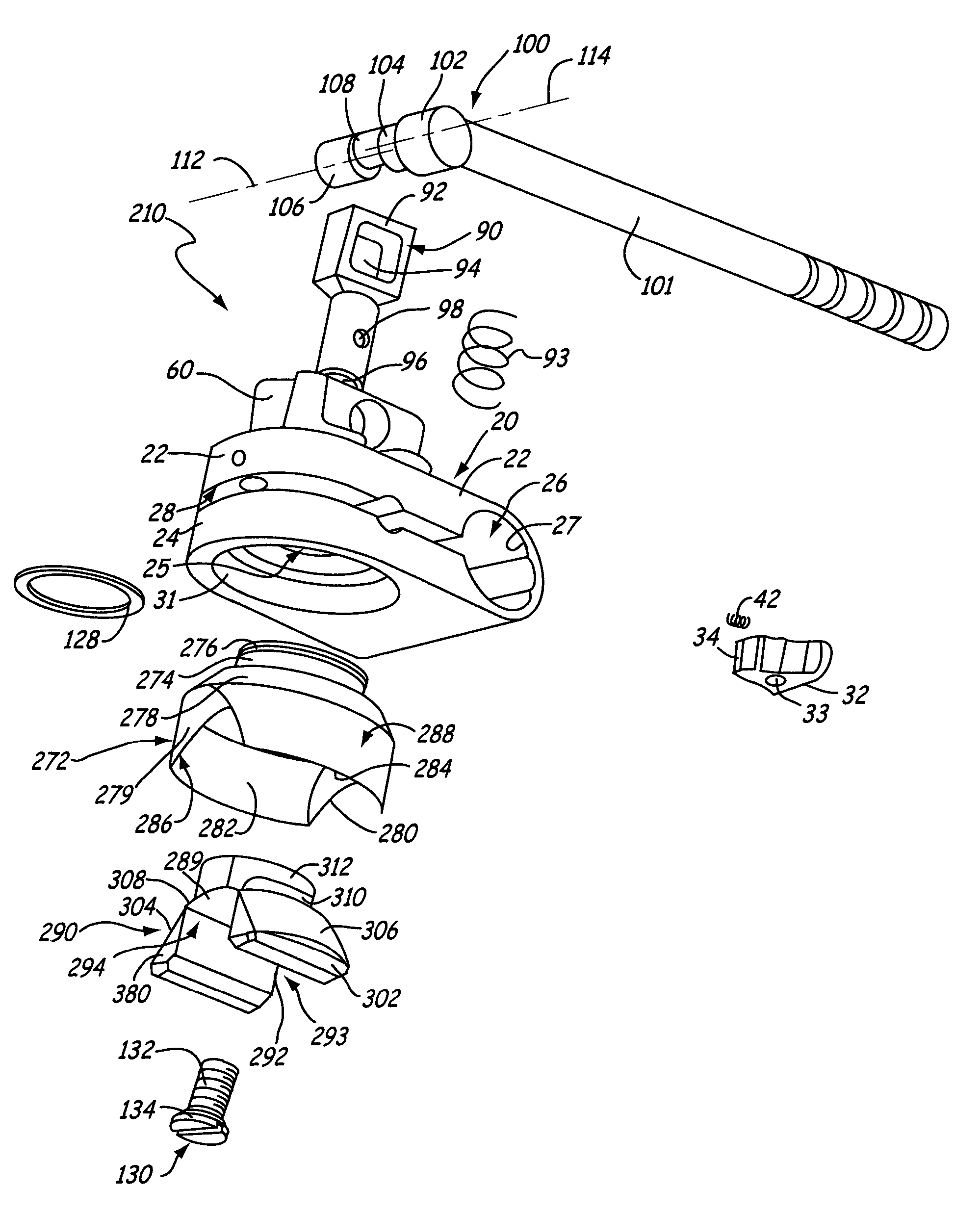
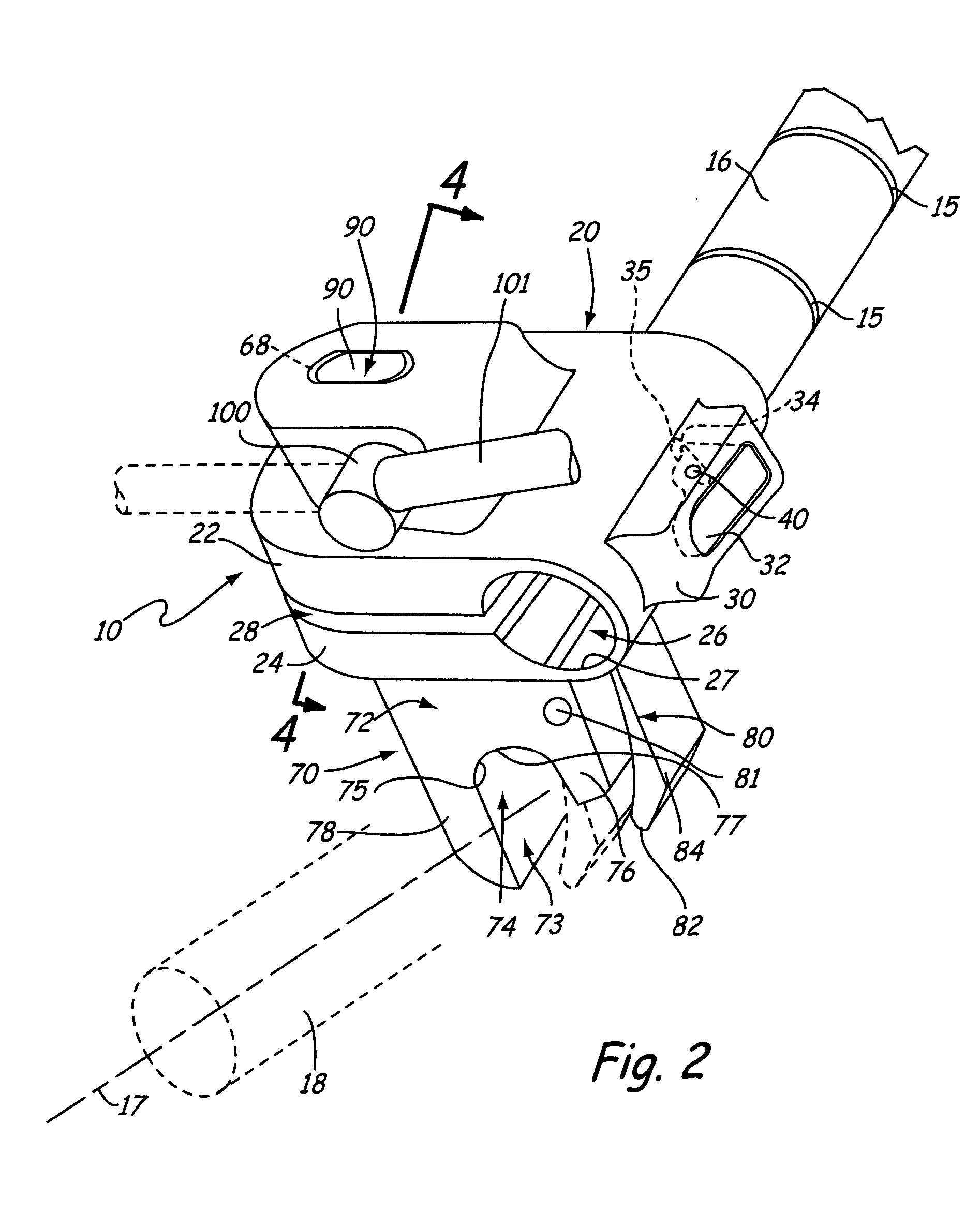
[0021] Referring to FIG. 2, the surgical clamp 10 includes a first clamping member 20 that engages the field post 16 and a second clamping member 70 that engages the retractor support apparatus 18. A shaft 90 is positioned through the first clamping member 20 and engages the second clamping member 70. An actuating mechanism 100 is coupled to the shaft 90 where the actuating mechanism 100 is positionable between a first position and a second position.

[0022] In the first position, the first and second clamping members 20, 70, respectively, are in a nonclamping position where the first clamping member 20 is positionable on the field post 16. The retractor support apparatus 18 is positionable within the second clamping member 70 and the second clamping...


PUM


Abstract

A surgical joint includes a first clamping member for engaging a first support member and a second clamping member for engaging a second support member. The first clamping member includes a clamping bore wherein the first support member is positionable within the clamping bore. The second clamping member includes a socket wherein the second support member is positionable within the socket. A shaft is disposed through the first clamping member and is in communication with the second clamping member. An actuating mechanism is coupled to the shaft wherein the actuating mechanism is positionable to force the first clamping member frictionally engages the first support member and the second clamping member frictionally engages the second support member.

Description

CROSS-REFERENCE TO RELATED APPLICATION(S) [0001] None. BACKGROUND OF THE INVENTION [0002] The present invention relates generally to a surgical clamp for use in mounting a retractor support apparatus with respect to an operating table. More particularly, the present invention relates to a clamp that can be positioned about the retractor support apparatus in a selected position. [0003] Prior to performing a surgical procedure requiring retraction, a retractor support apparatus is typically constructed about a surgical site. The retractor support apparatus is attached to a field post that is attached to a surgical table with the field post extending upwardly from the surgical table. [0004] The retractor support apparatus extends over the surgical table and can include as little as one support member or numerous support members. Retractors and other surgical equipment are positioned about the surgical site by being secured with a clamp attached to the retractor support apparatus. [0005...

Claims


Application Information

Patent Timeline
IPC IPC(8): A61B1/32A61B17/02A61B19/00
CPCA61B1/32A61B17/02A61B2019/268A61B2019/267A61B19/26A61B90/57A61B90/50A61B2090/571
Inventor BJORK, TODD M.SHARRATT, TODD WILLIAMBERG, CHRISTOPHER LEE
Owner MINNESOTA SCI
Learn More